

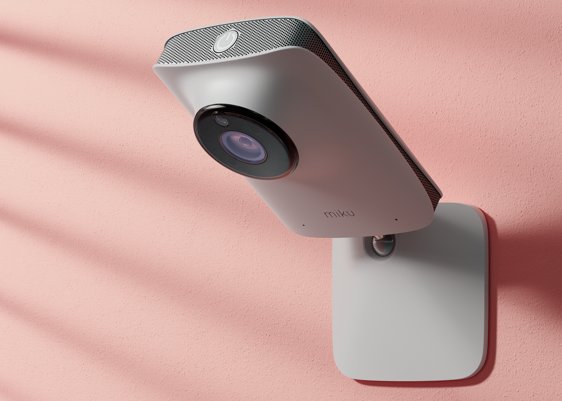
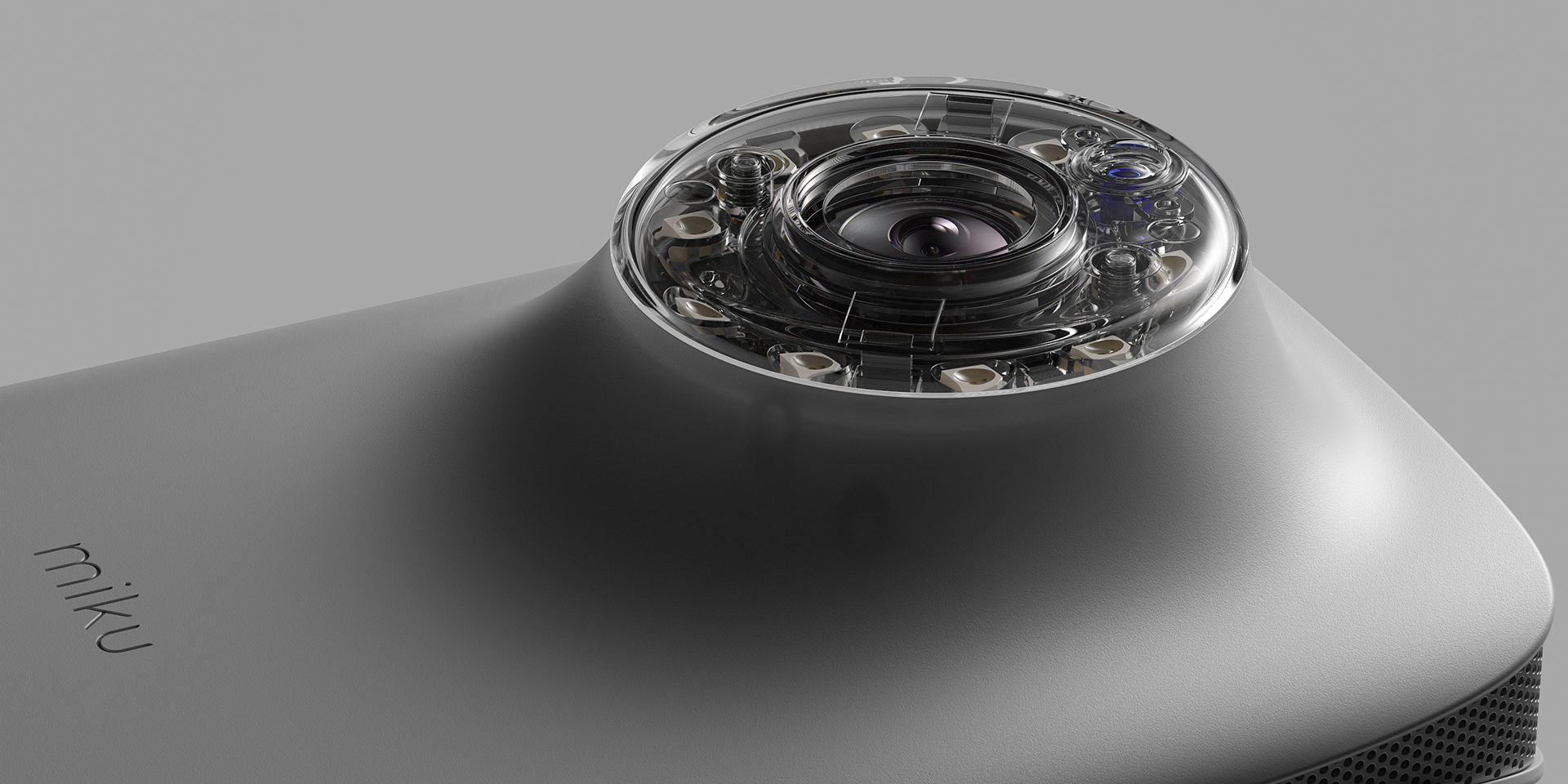
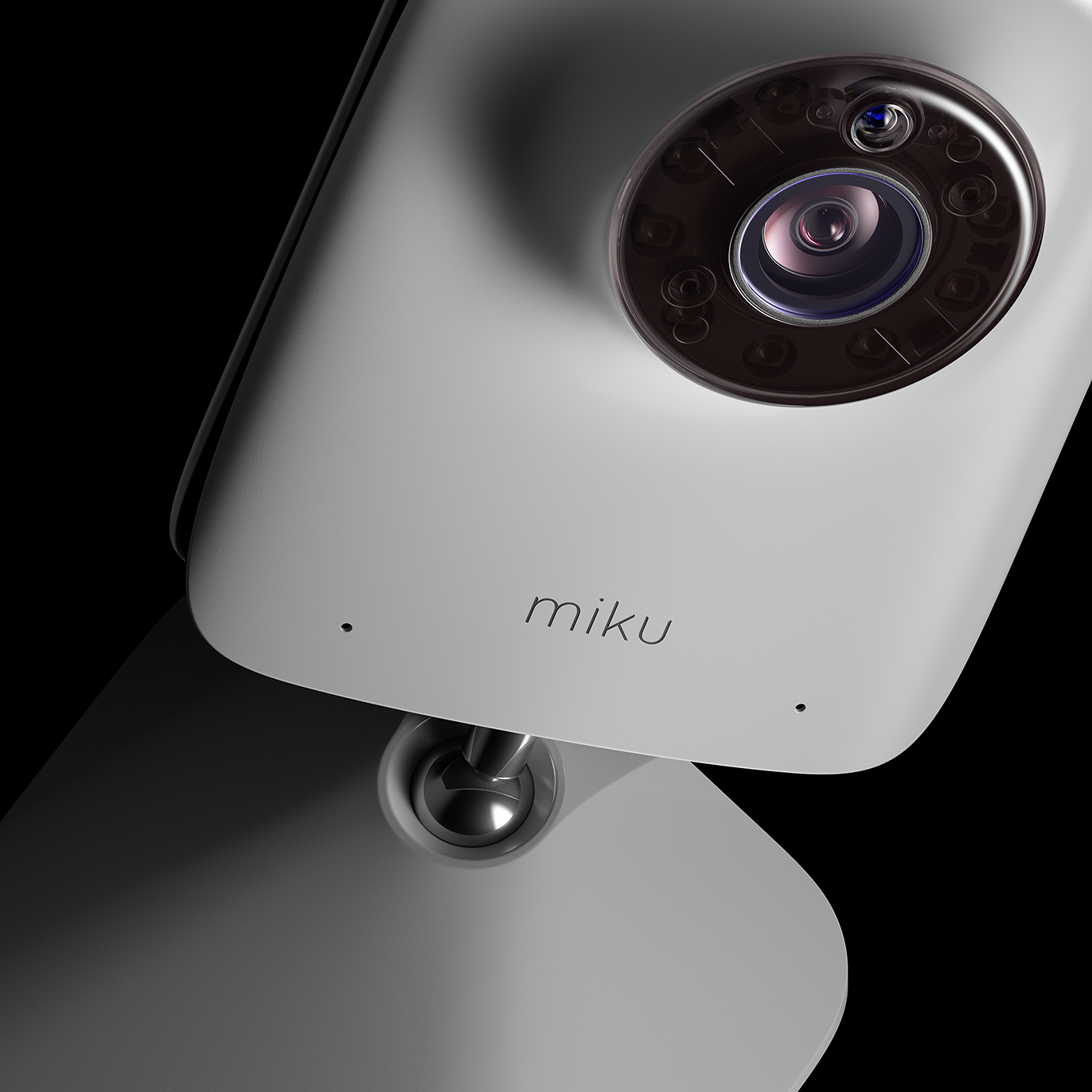
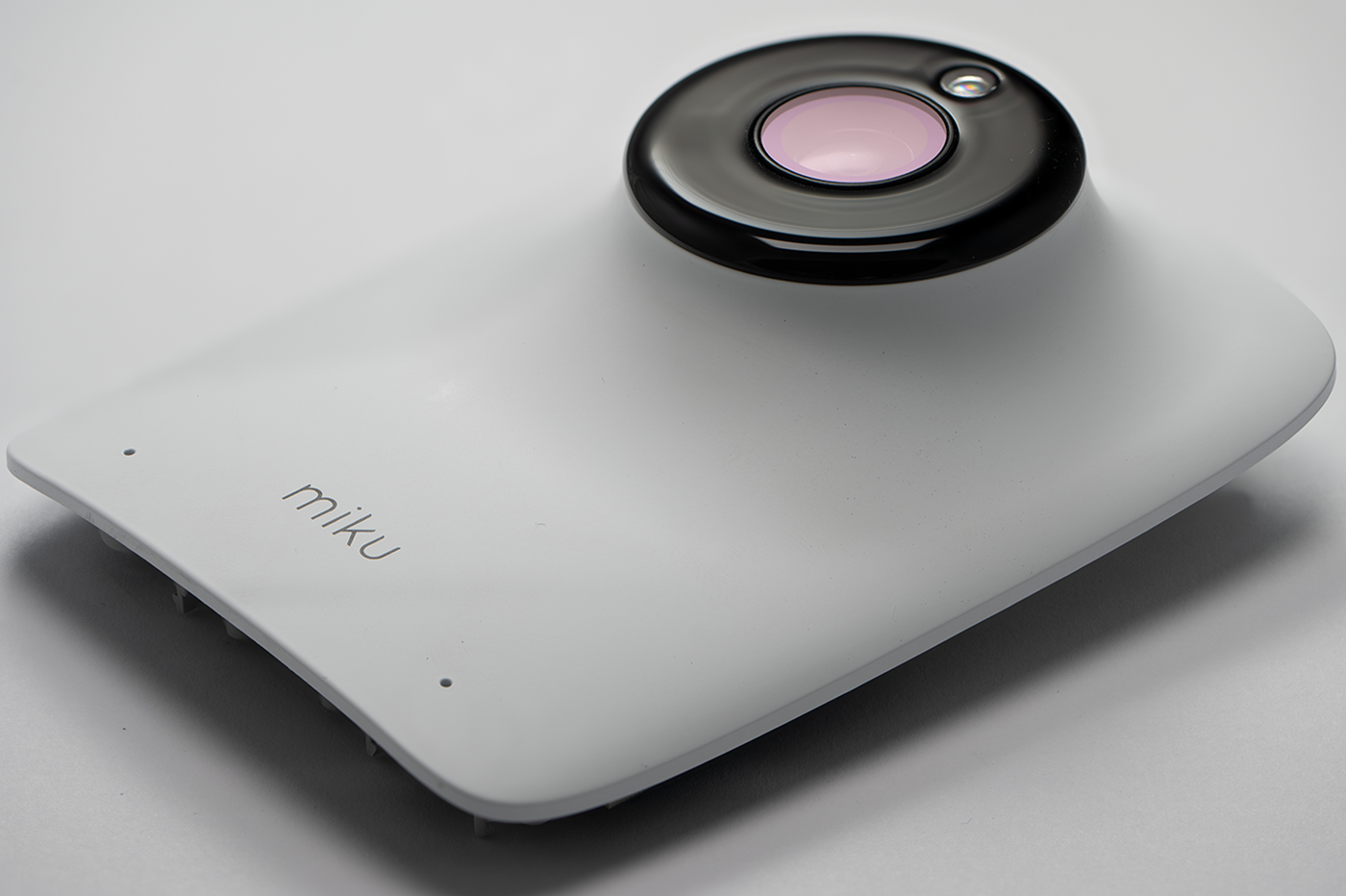
The Contact-Free Baby Monitor
Tracks Breathing, Sleep Patterns, and Nursery Conditions, Contact-Free.
Miku creates products that make it easy to monitor and understand your child’s health and wellness.
The original product page: https://mikucare.com/
Introduction
MIKU is my spare-time study project, inspired by my previous freelance experience with this brand.
For this educational journey, I wanted to create everything from scratch myself — including reverse engineering, 3D modeling, texturing, shading, and lighting.
For this educational journey, I wanted to create everything from scratch myself — including reverse engineering, 3D modeling, texturing, shading, and lighting.
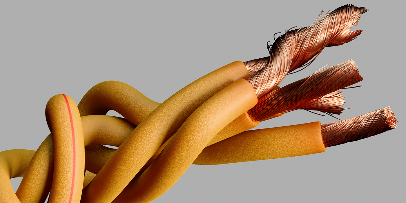
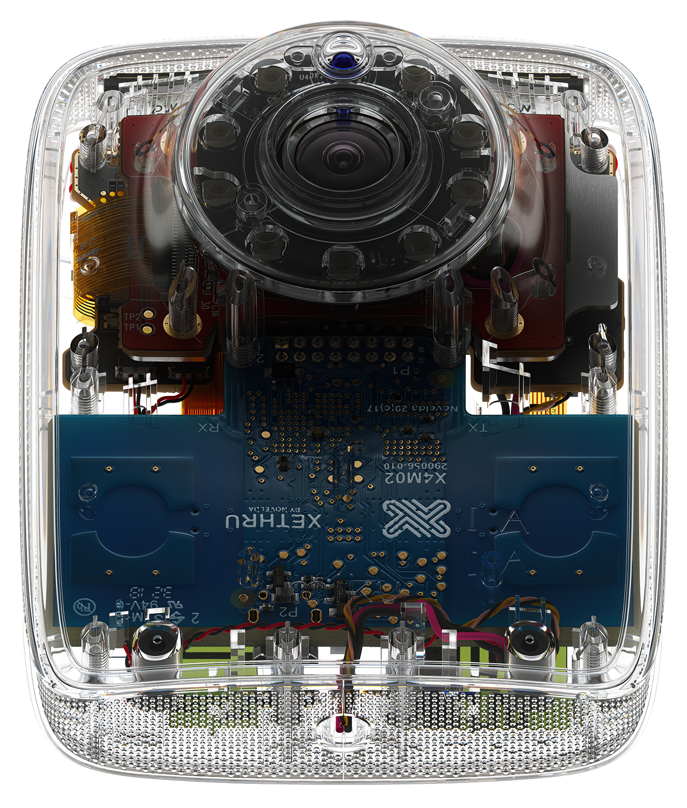
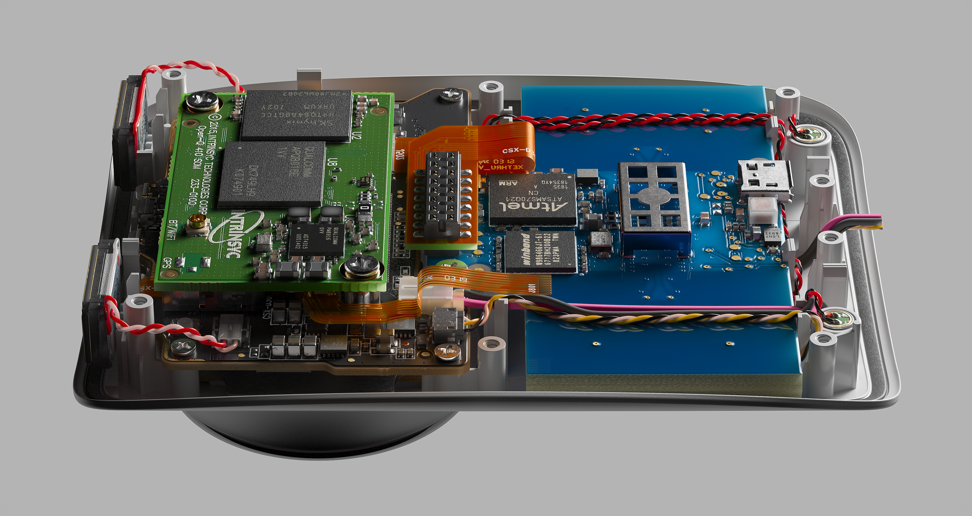
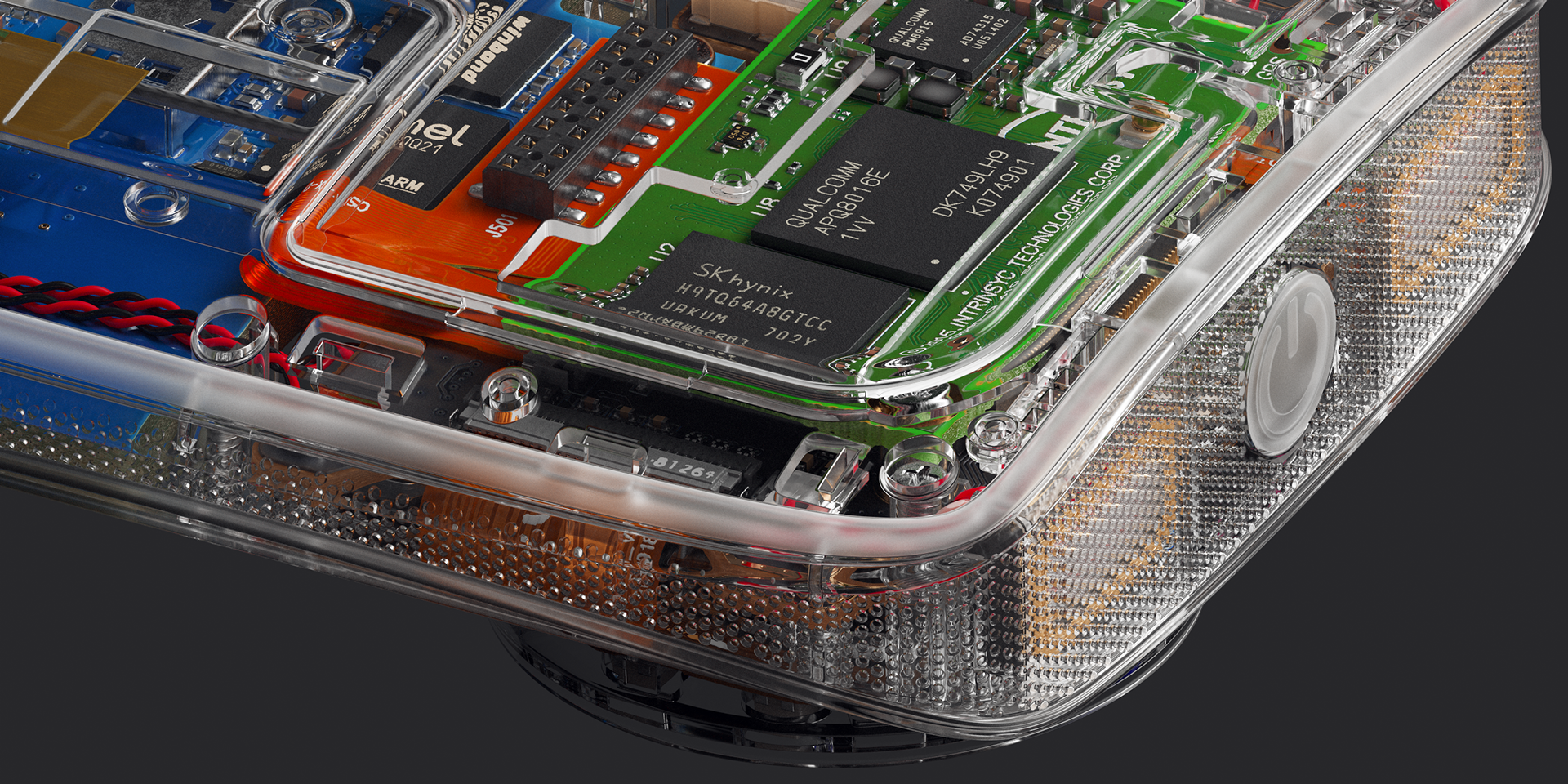
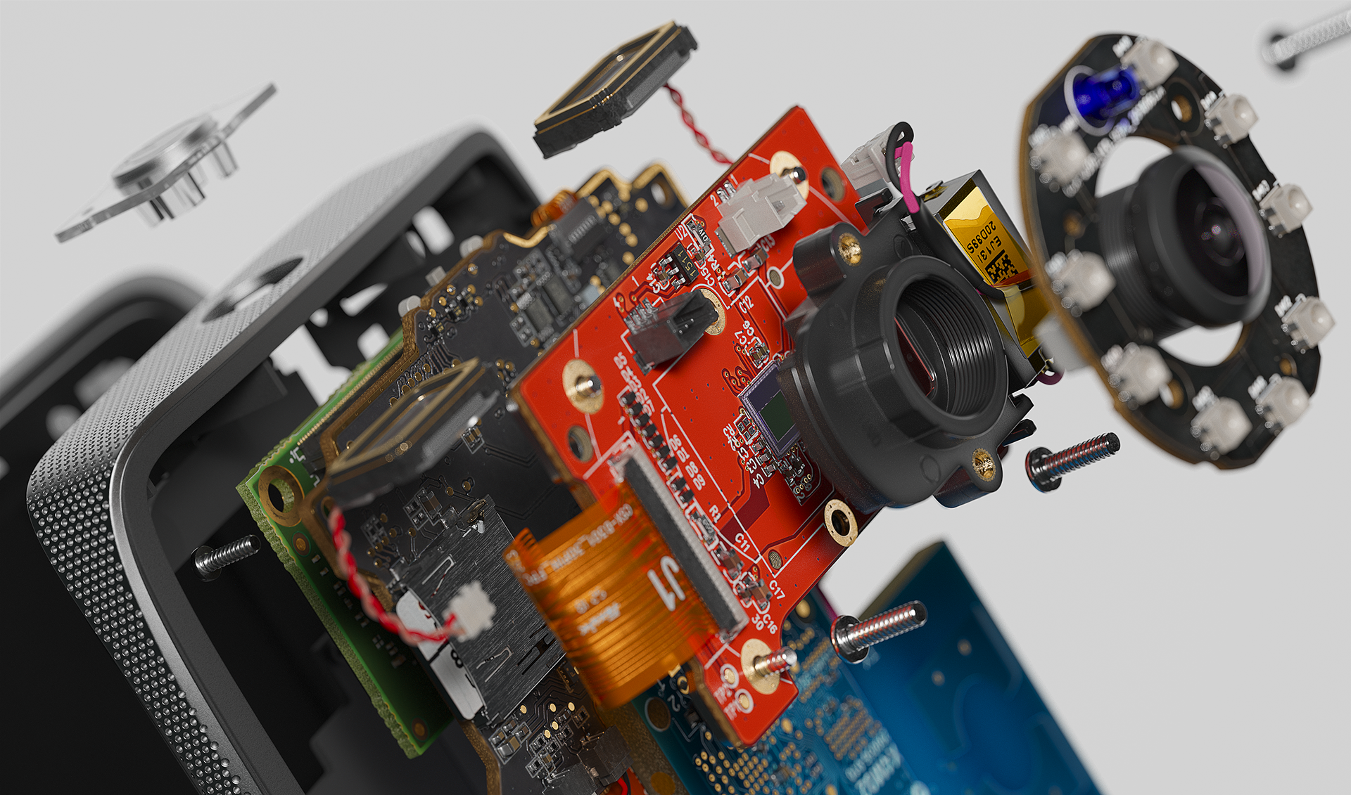
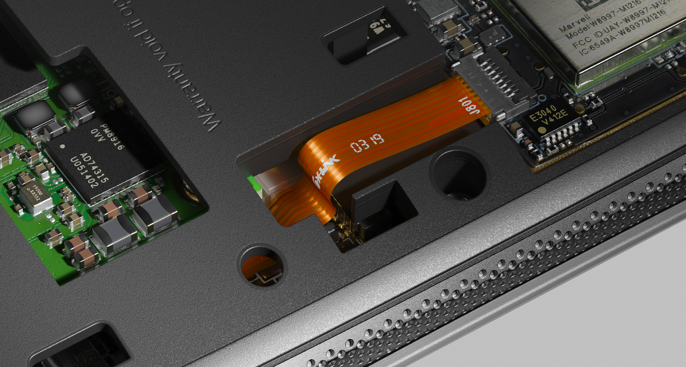
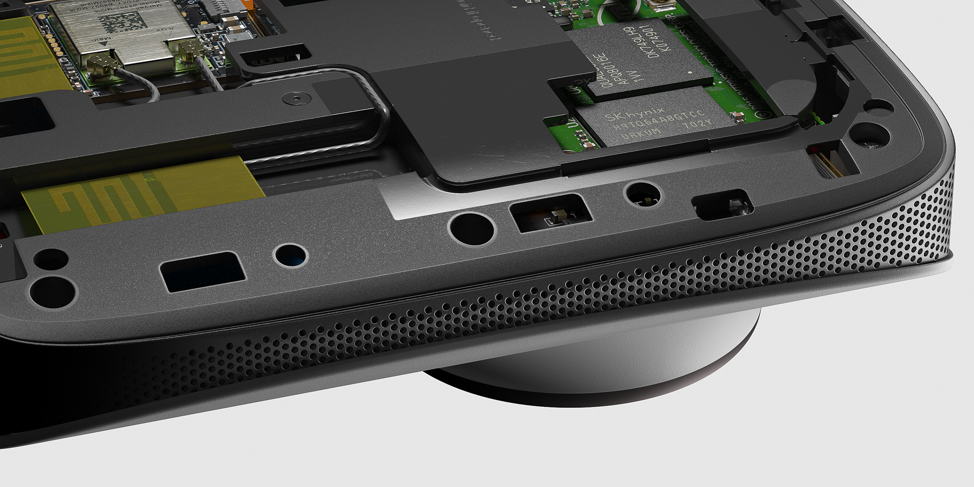
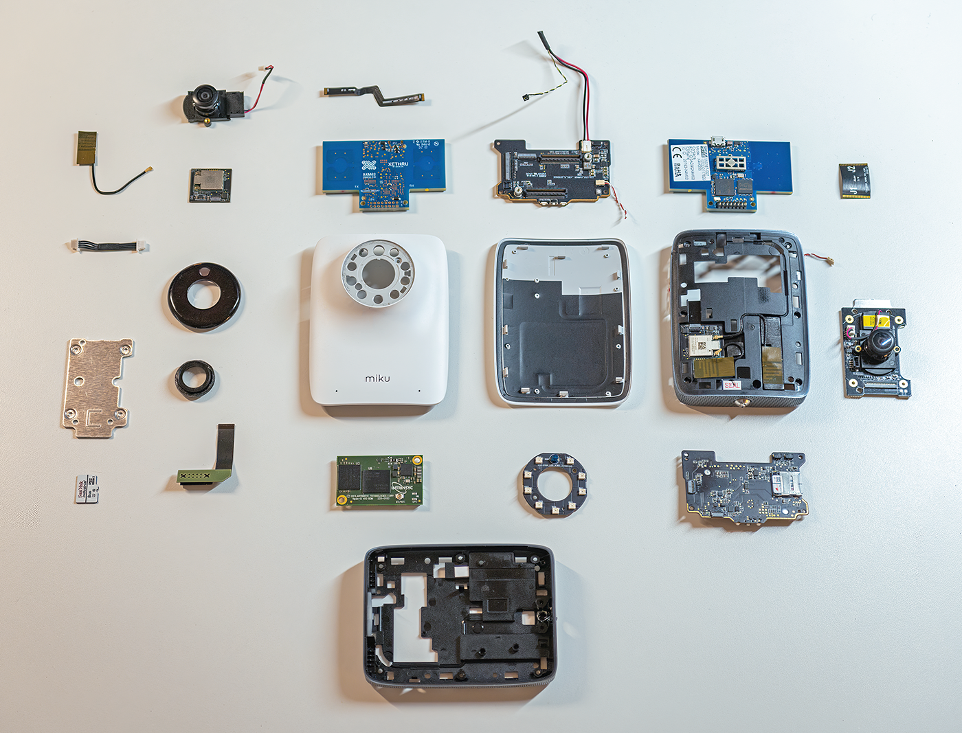
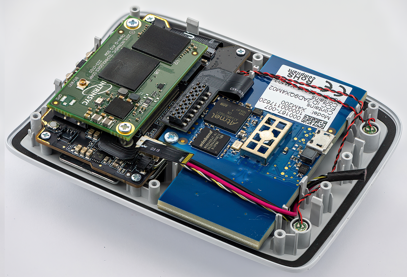
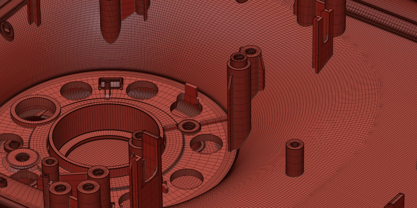
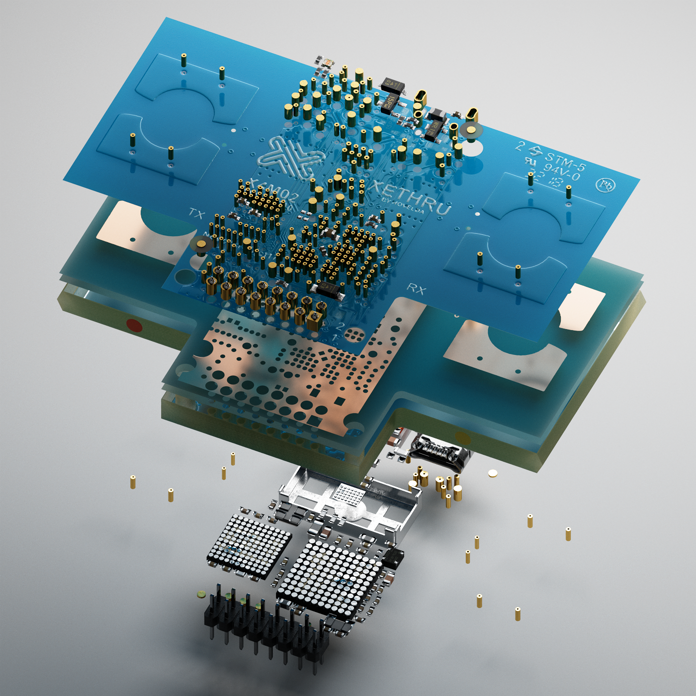
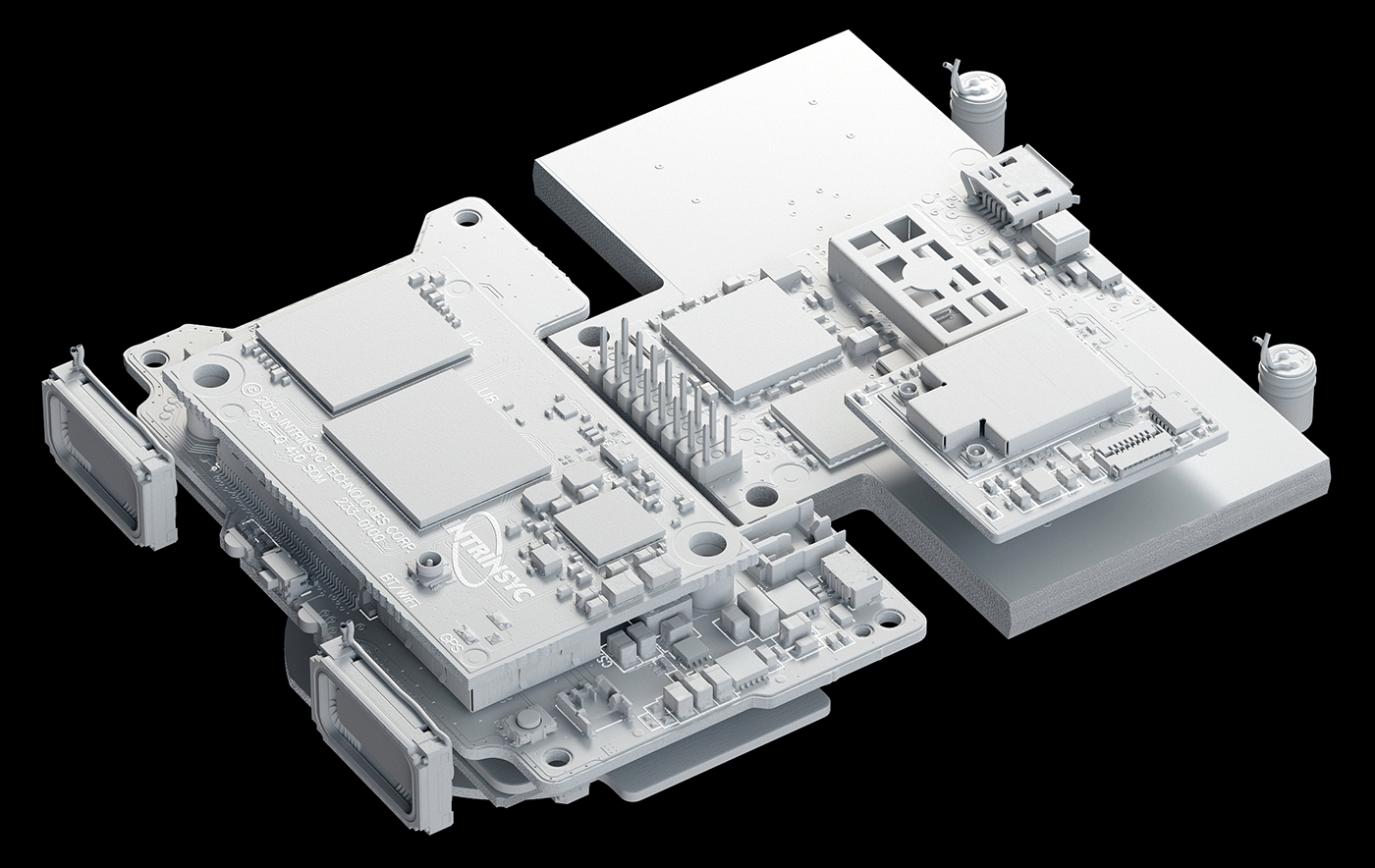
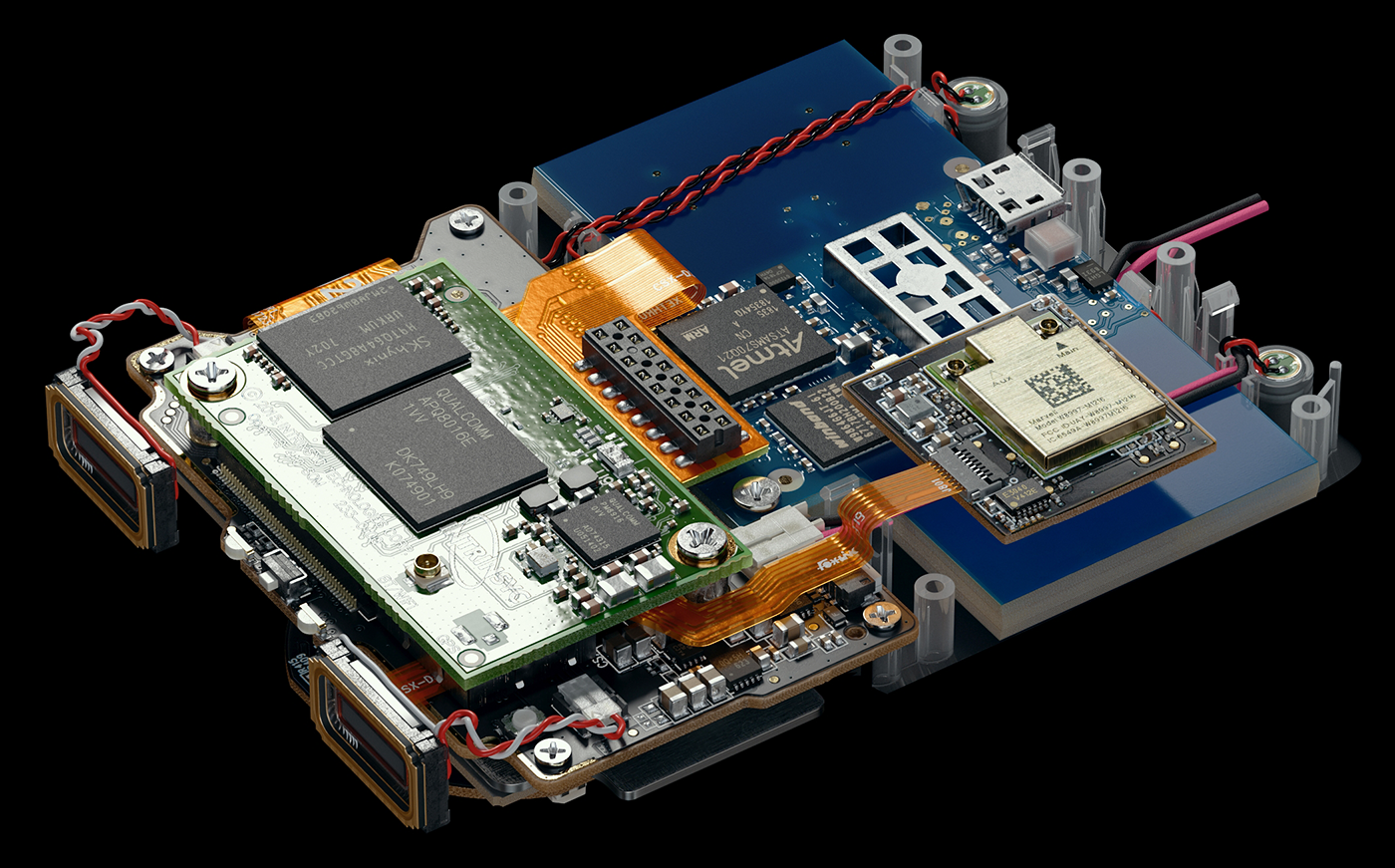
Internal Structure Images and PCBs
I enjoyed the opportunity to showcase the internal PCBs and electronic components, as I’ve always wanted to work with this type of engineering aesthetics as a CG artist.
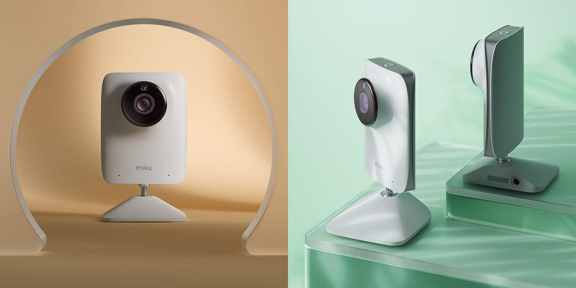
I used 3ds Max for modeling and the FStorm GPU rendering engine for the internal renders. For the exterior product renders, I worked in C4D with Redshift.
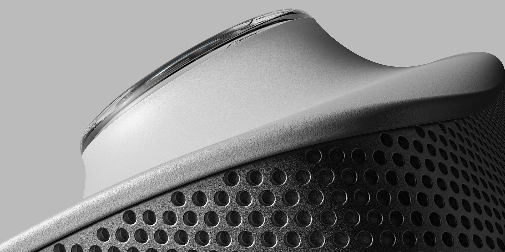
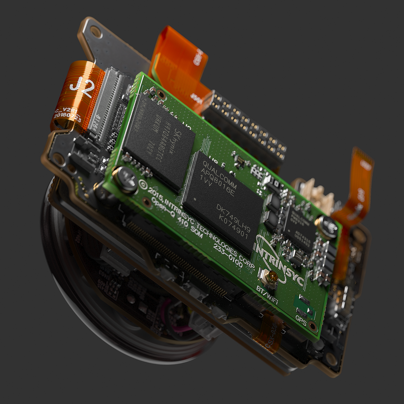

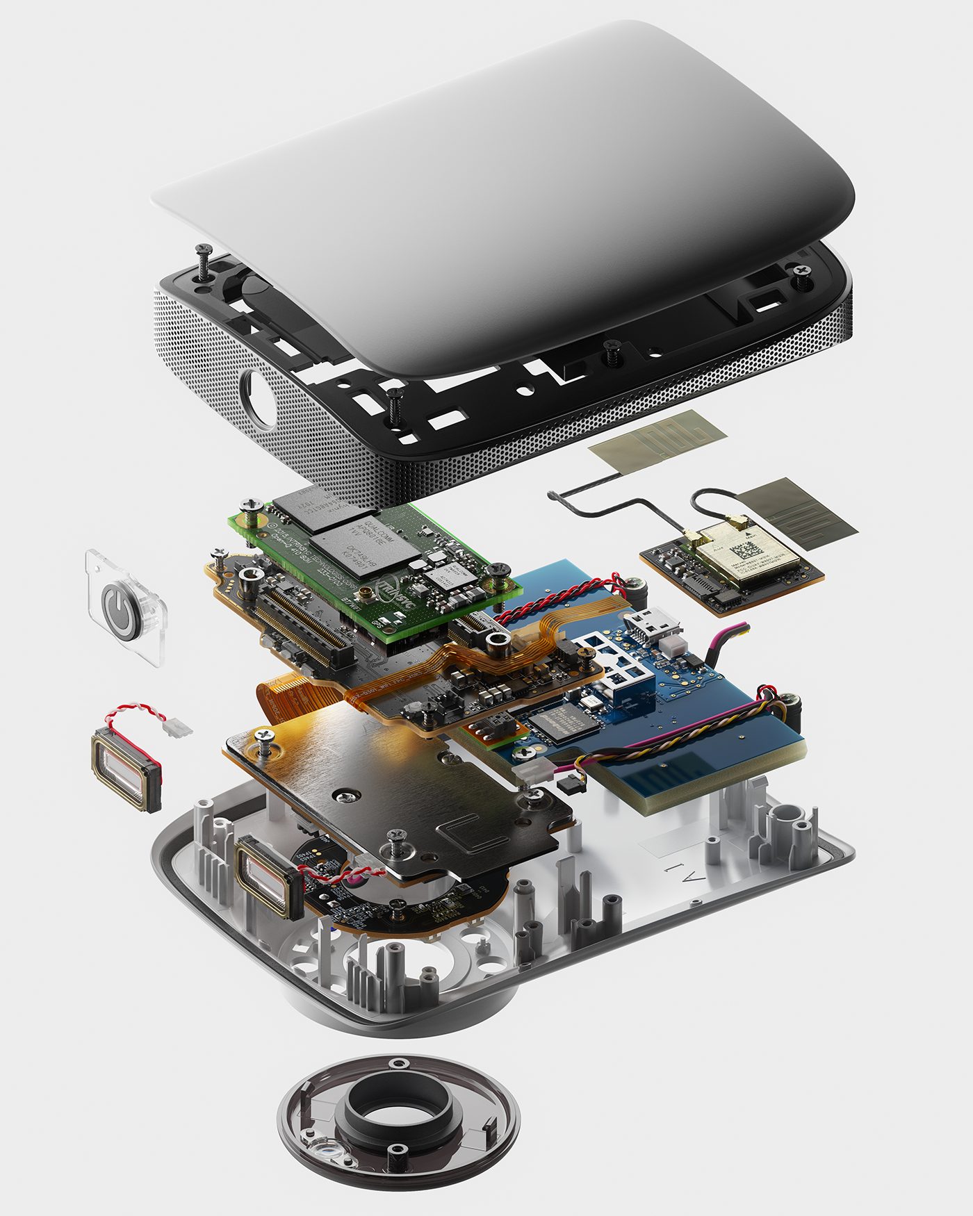
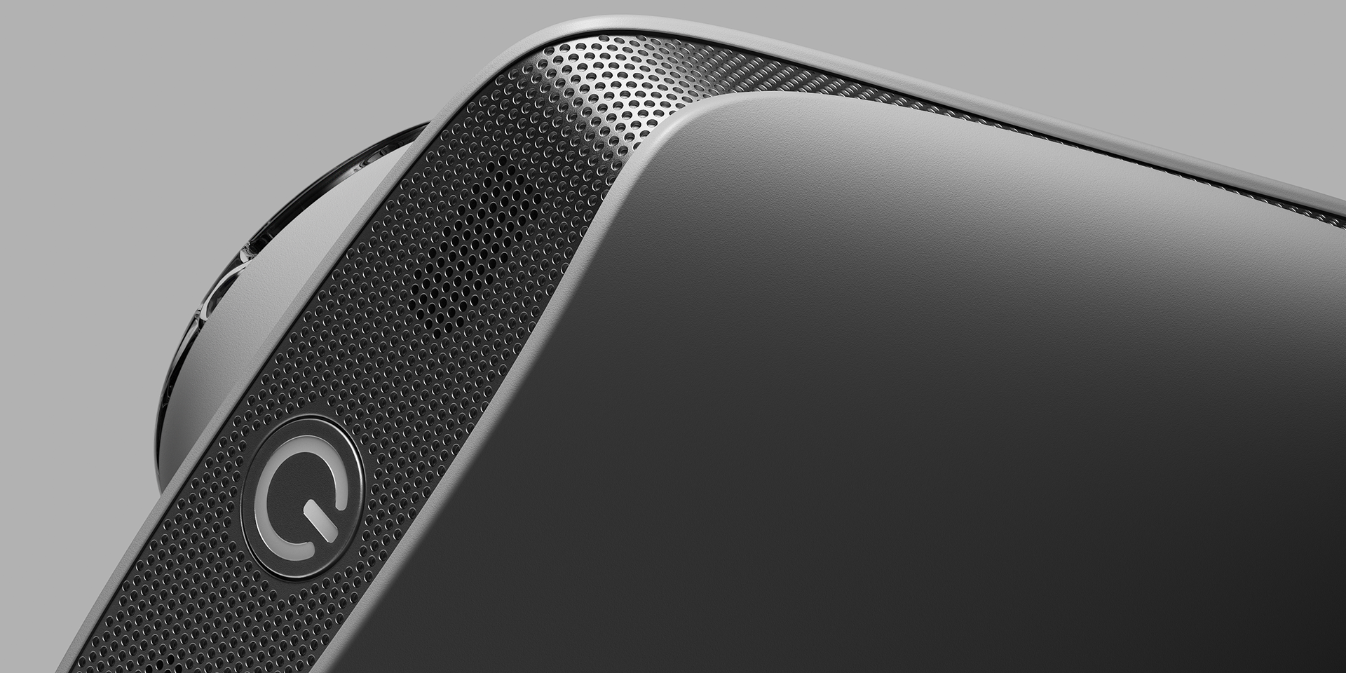
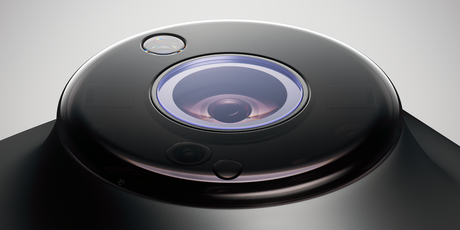
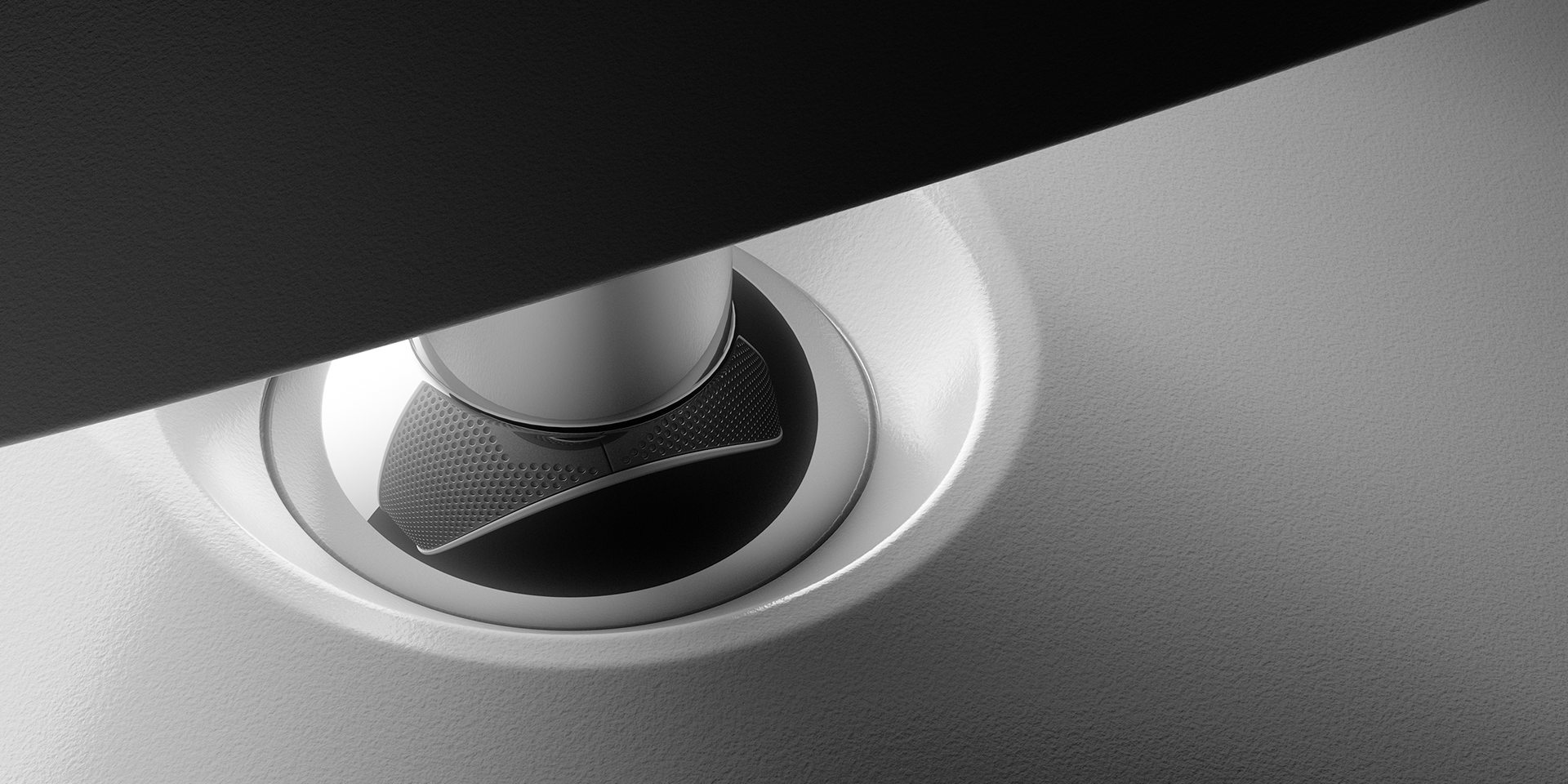
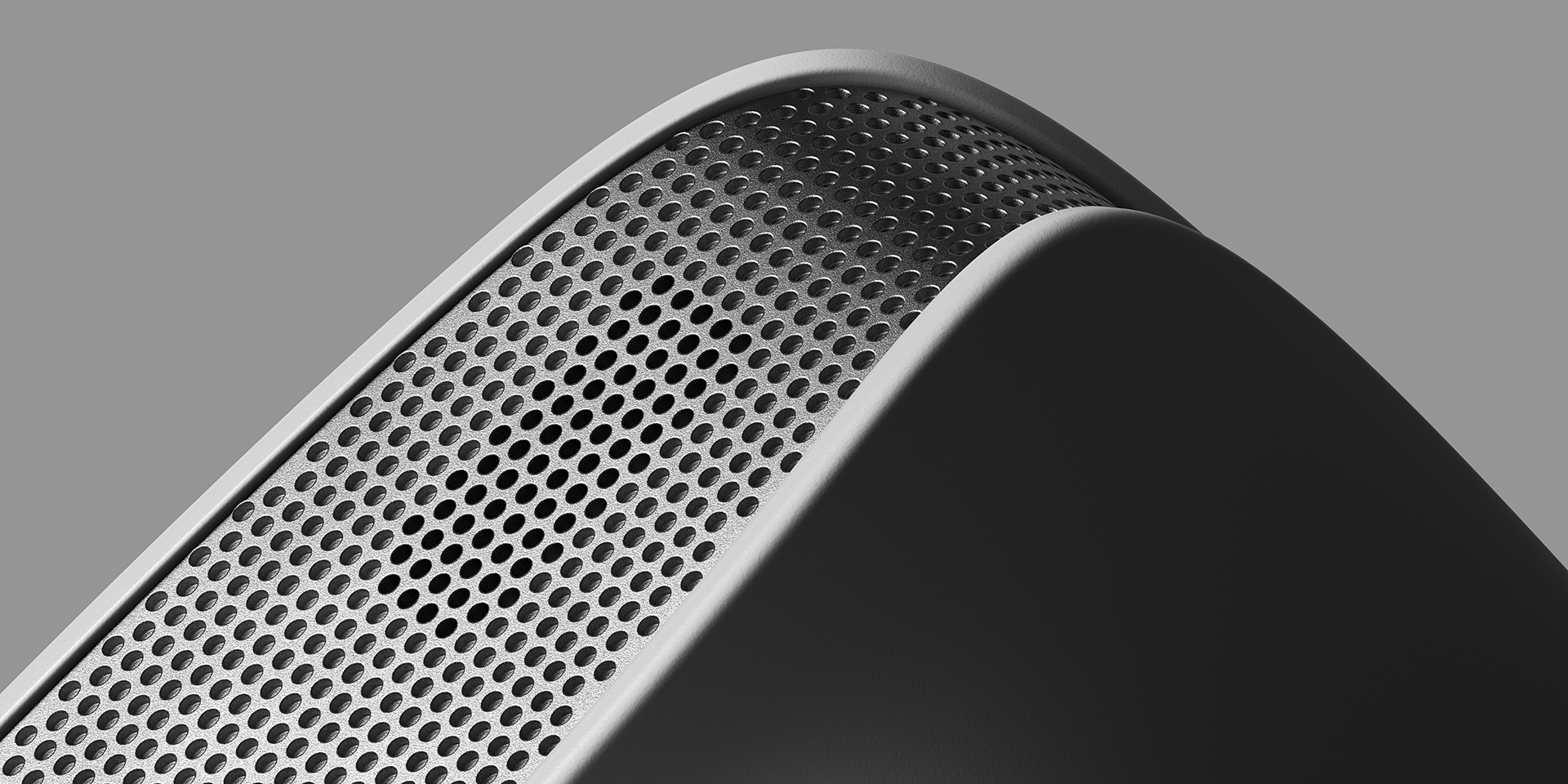
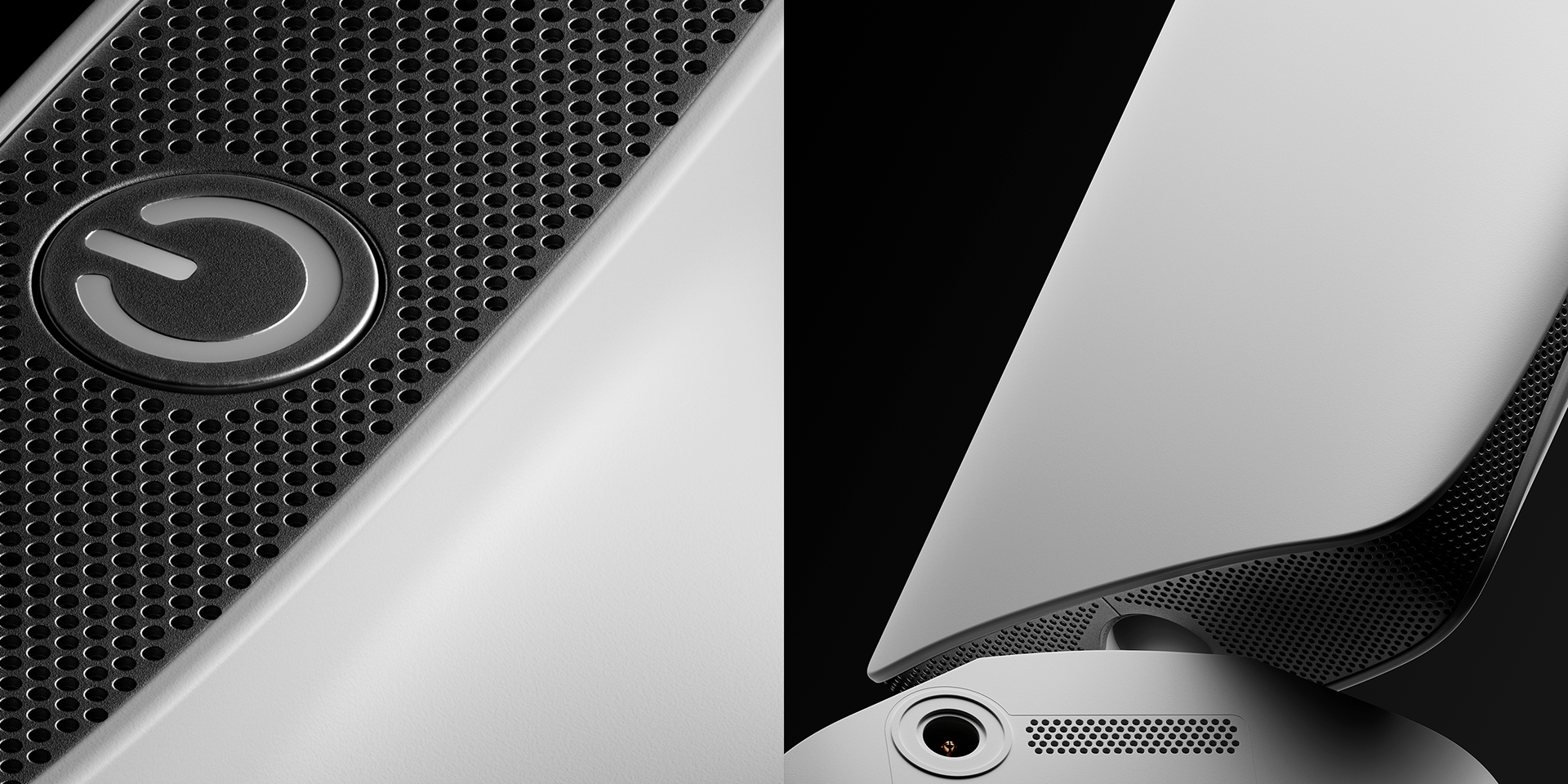
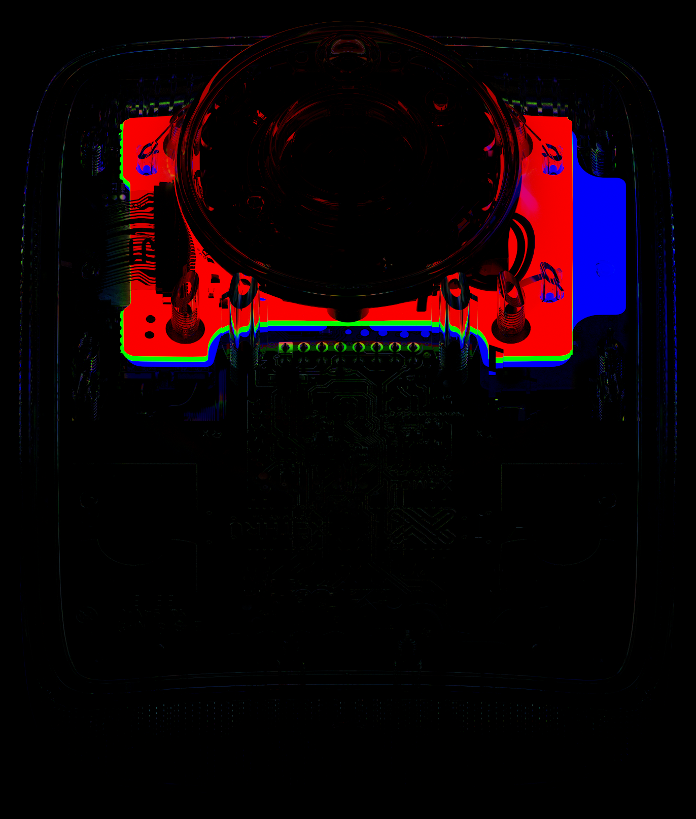
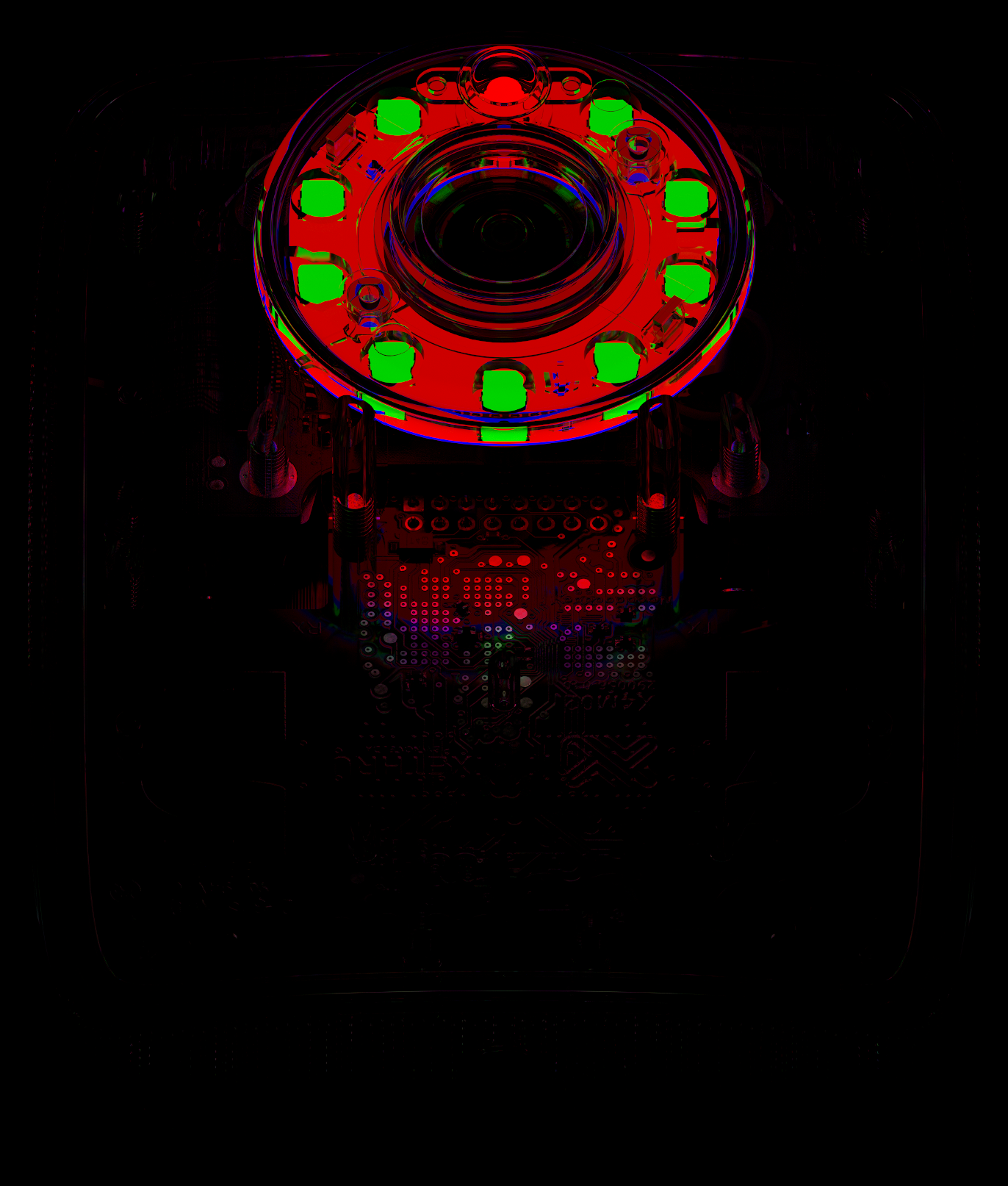
Studio Noir Renders
During the process, I decided to run another exercise — rendering with the low-key technique. I thought it would be interesting to try lighting each scene with only a single light emitter.

Some of the Process and Behind the Scenes
For the next stage of work, I needed reference information on the real PCB assemblies. I ordered three used MIKU kits on eBay to disassemble and reverse engineer.
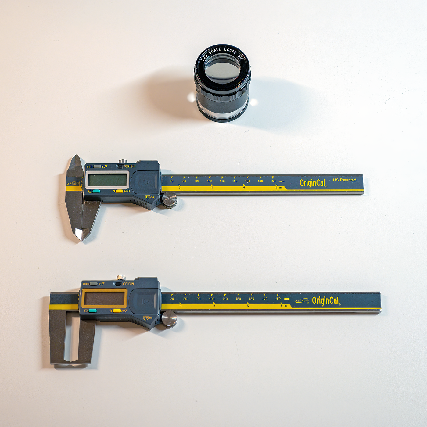
My main reverse engineering tools were a pair of digital calipers (for both external and internal measurements), a magnifying glass with a dimensional grid, and macro photography.
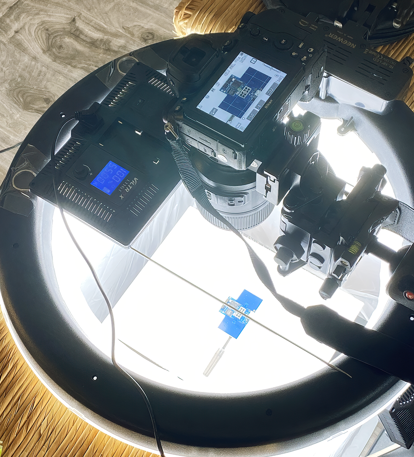
I decided to photograph each board from both sides at the highest possible resolution, so the images could serve not only as reference but also as a direct source.
The shooting was done with a Nikon Z7II 45 MP camera and a Nikkor 105mm f/2.8 VR lens for macro work.
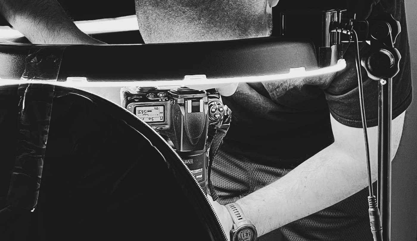
Since some boards were glossy and reflective, I had to watch the highlights carefully, avoiding overexposure and harsh specular reflections.
The lighting setup included a 45×45 cm lightbox, five LED lights, and one ring light.
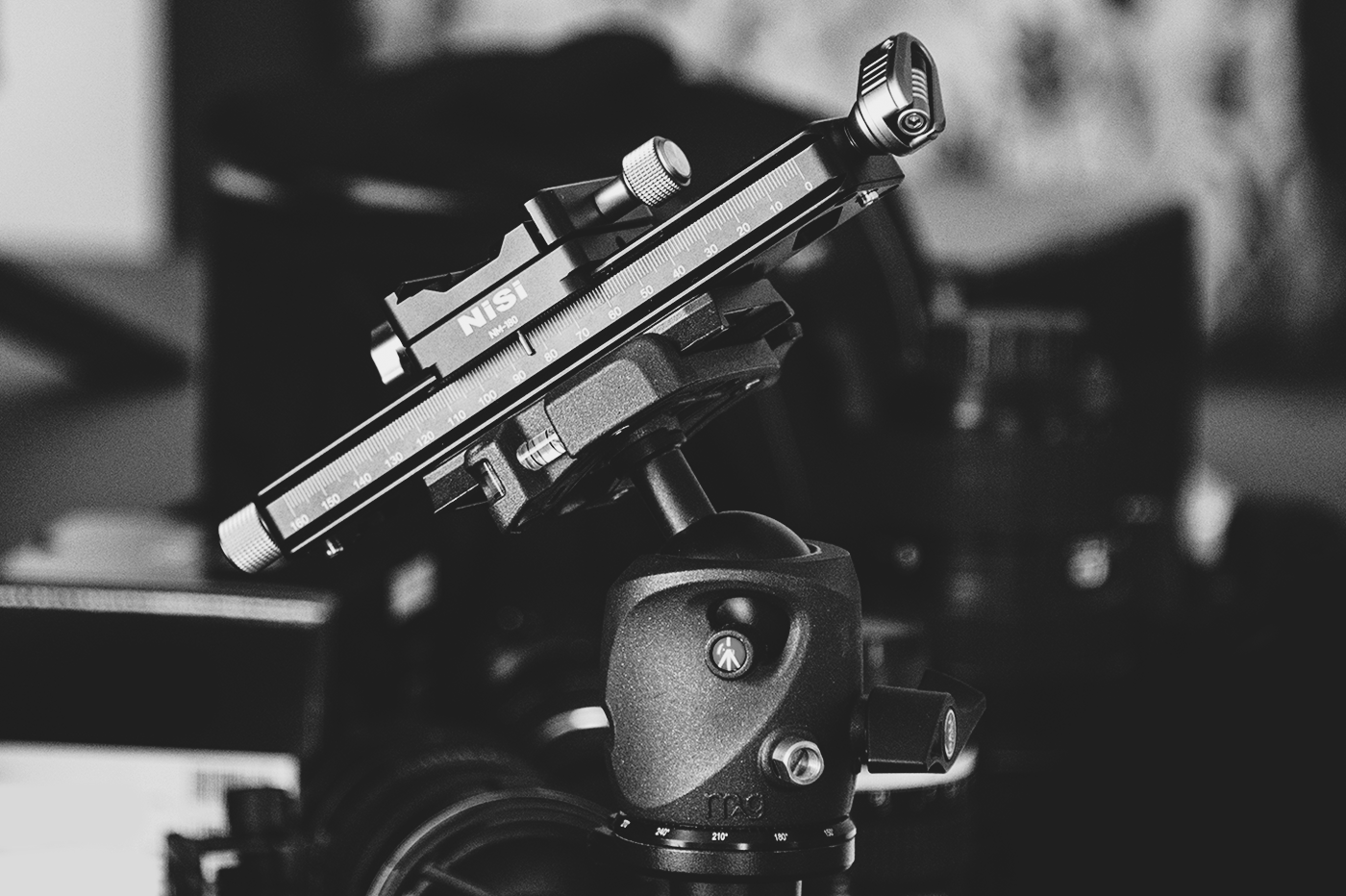
Camera Focusing Rail for macro photo-shooting
Since the thick PCB coating creates a polarizing effect, it made sense to use a polarizing filter to control the amount of light in the reflections.
The f/2.8 macro lens has a very shallow depth of field, even with the aperture closed down to f/16.
To get full sharpness, I took 10–15 shots for each side of the board, moving the camera along the Z-axis with a focusing rail.
These shots were later merged using the photo-stacking technique.
To get full sharpness, I took 10–15 shots for each side of the board, moving the camera along the Z-axis with a focusing rail.
These shots were later merged using the photo-stacking technique.
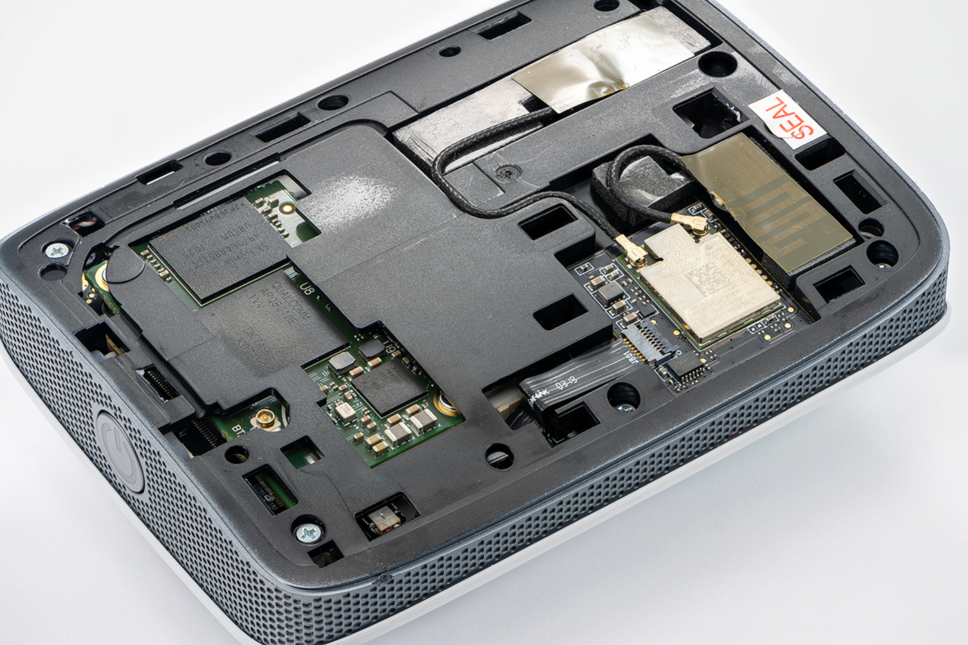
Some of the reference photos of the MIKU baby monitor
The final resolution of the stacked textures was around 15000pix wide, which allowed me to use them for anything I need - vector tracing, creating masks, and shader layers.
I used the Helicon Focus software to stack the 15 photos into one sharp image. https://www.heliconsoft.com/
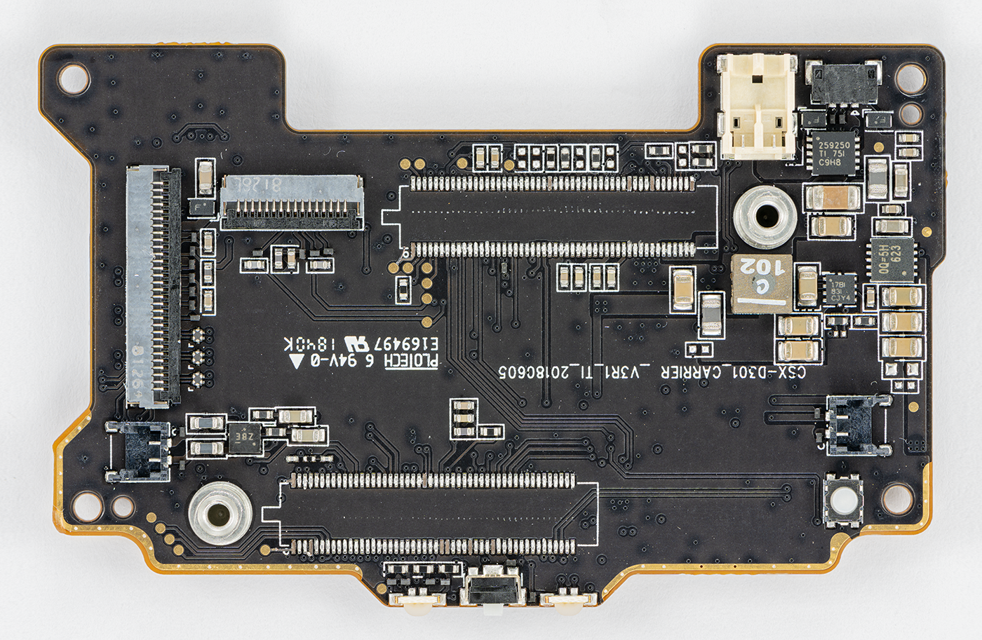
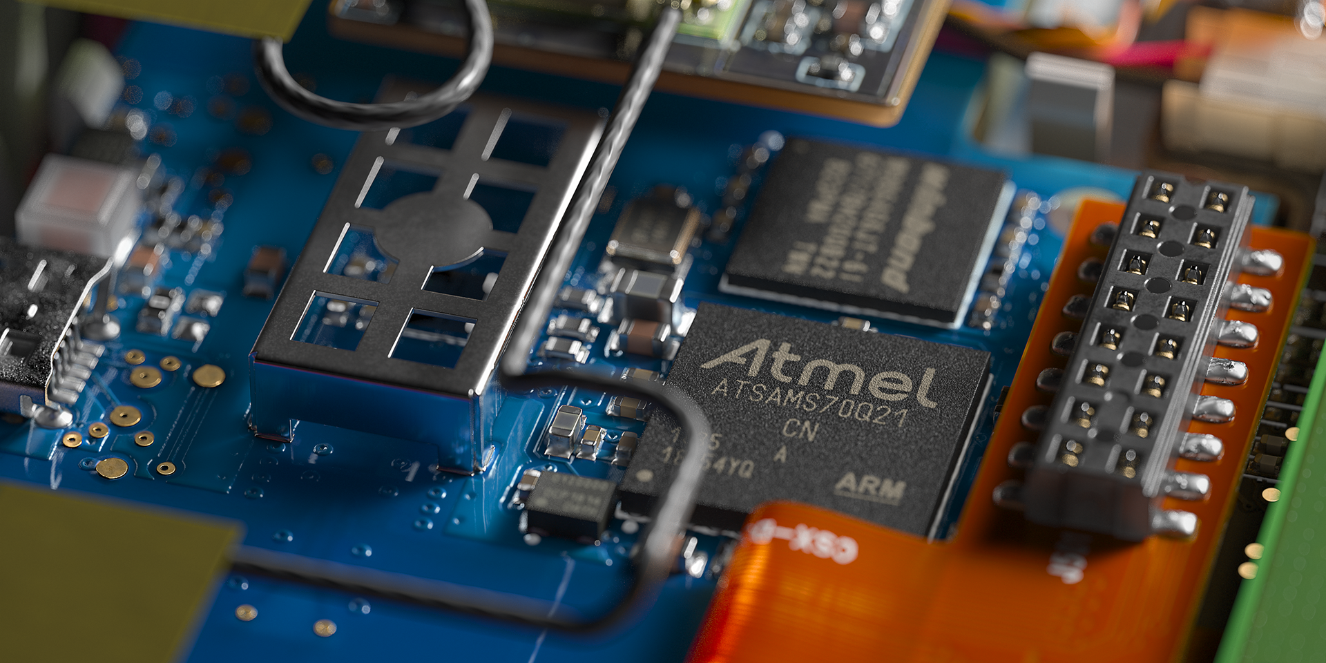
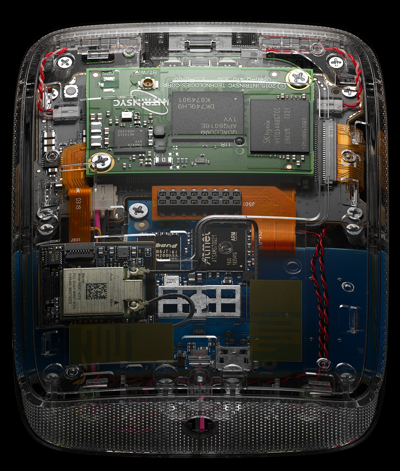
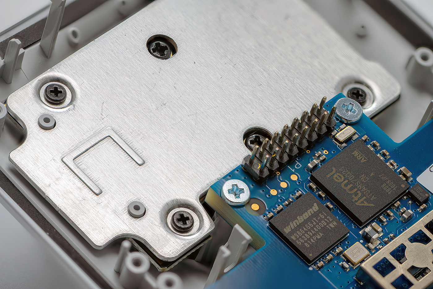
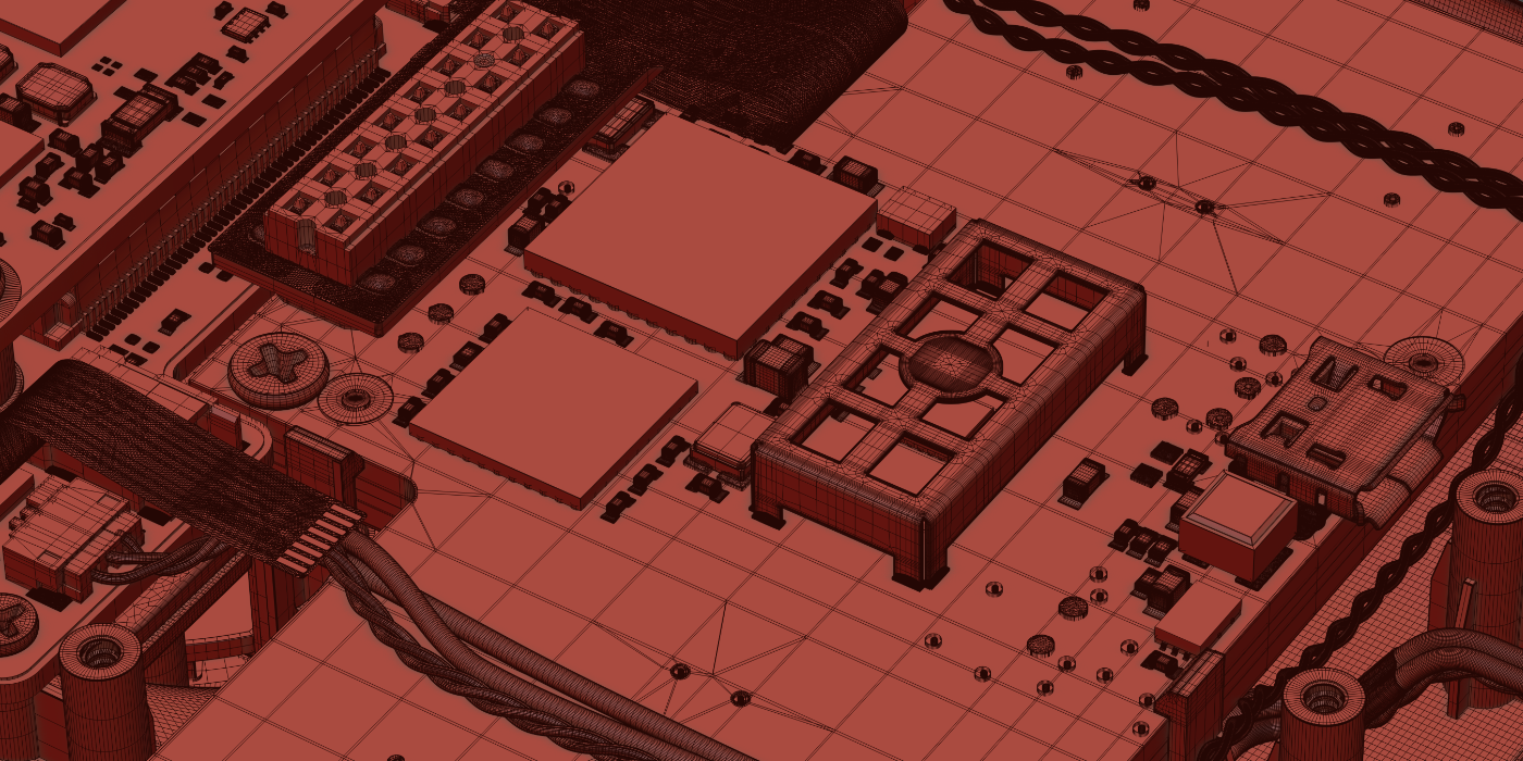
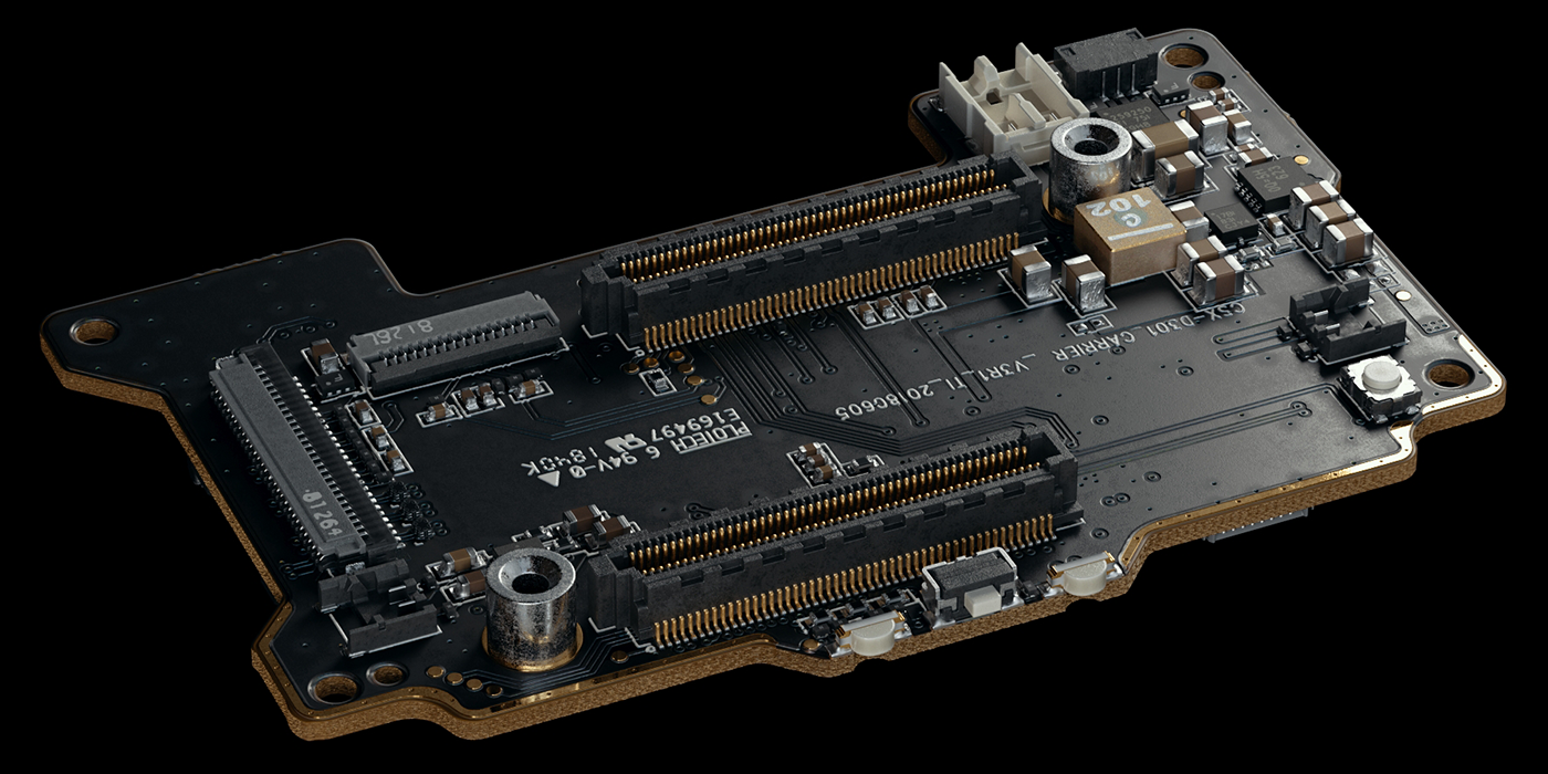
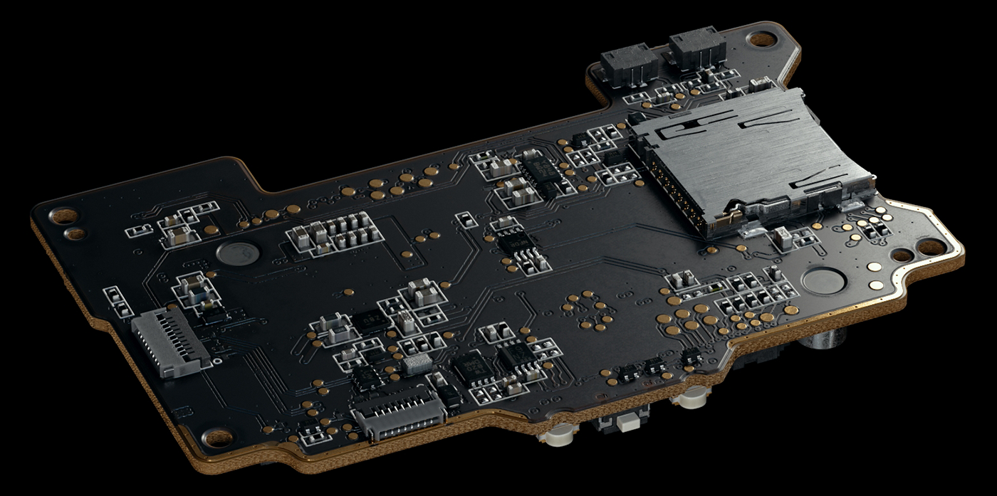
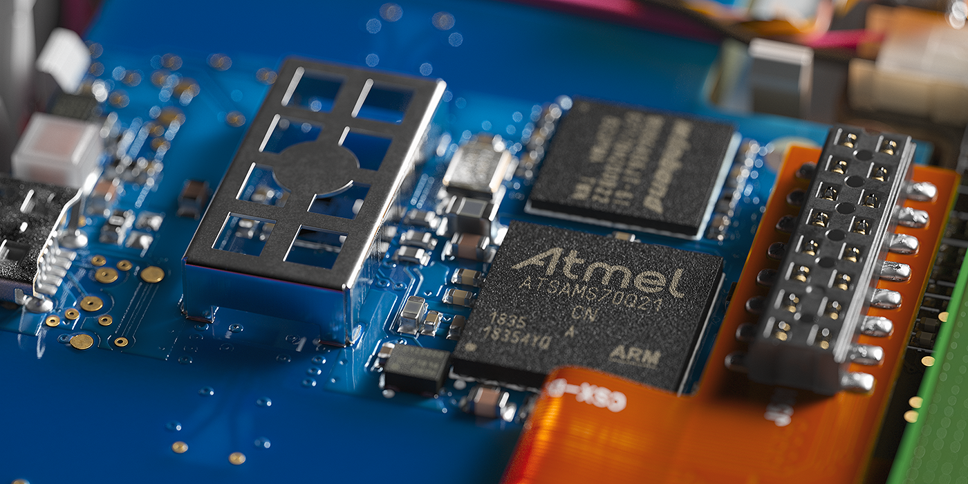
Memory Controlling PCB Source Photo
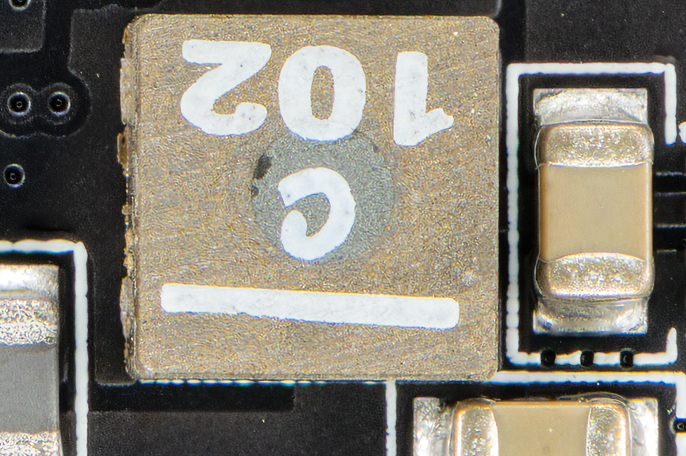
Memory Controlling PCB Source Photo 100% crop
While working on the PCB models, I used different techniques.
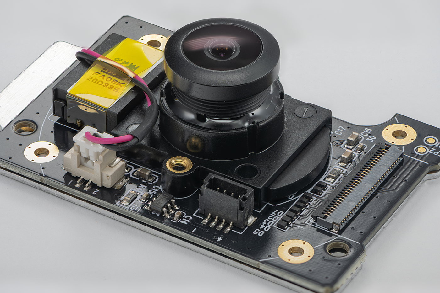
For example, to create the camera controller board, I traced all the paths in Illustrator and used this vector as a base for modeling. This approach worked well because the paths on this board were deep enough and not too numerous.
For example, to create the camera controller board, I traced all the paths in Illustrator and used this vector as a base for modeling. This approach worked well because the paths on this board were deep enough and not too numerous.
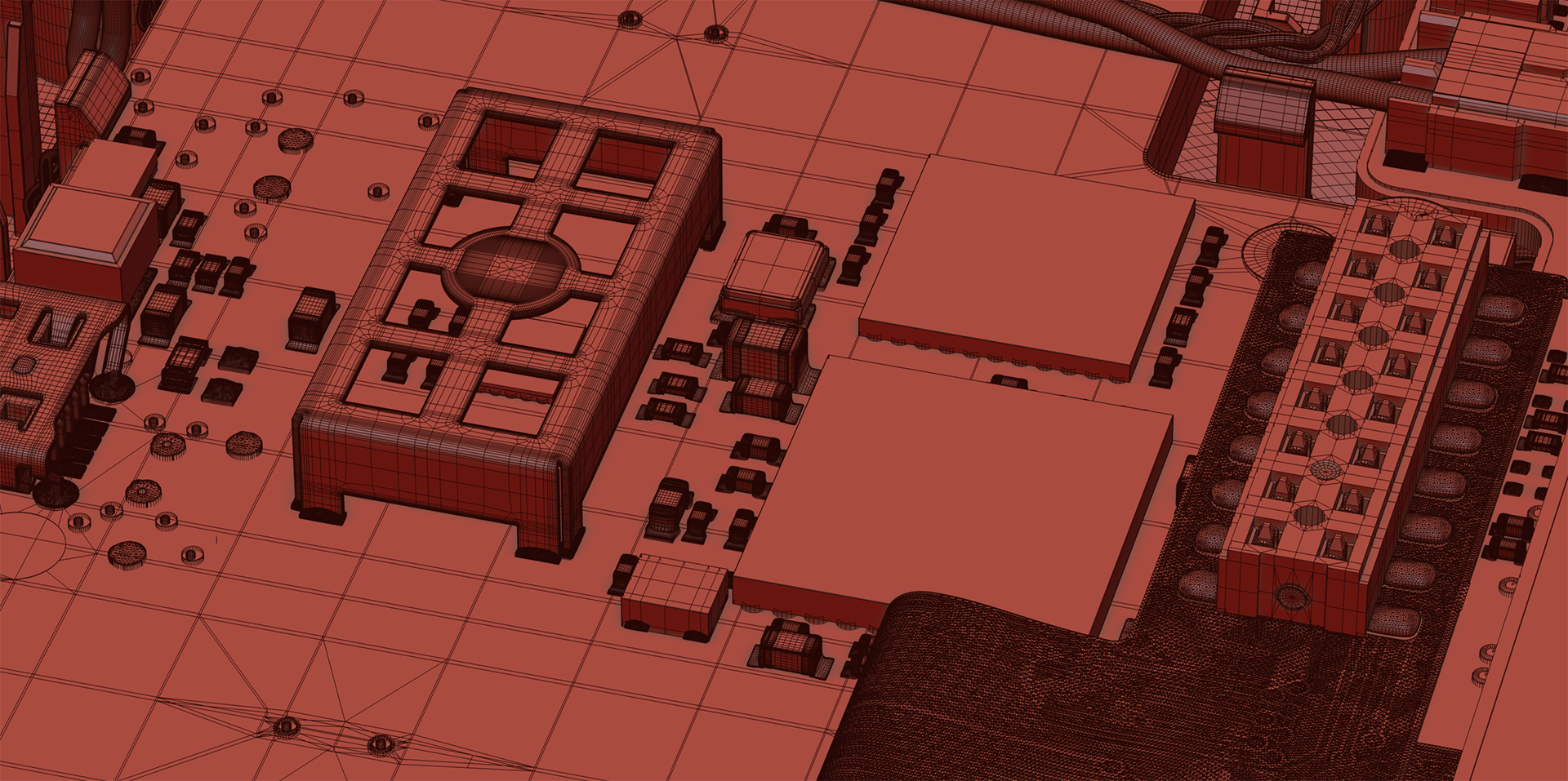
This camera PCB assembly also had tracks on only one side, as the other side is covered with a metal shield. The tracks on this board were modeled as real geometry.
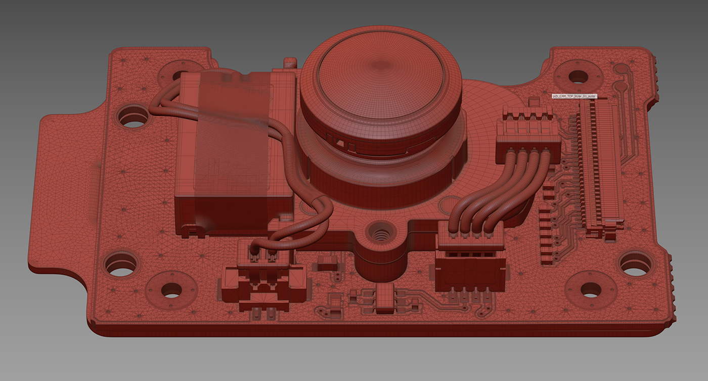
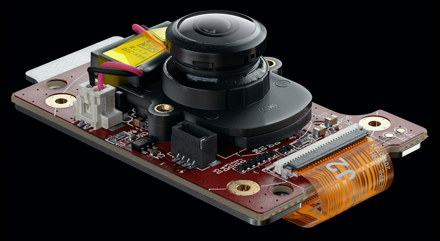
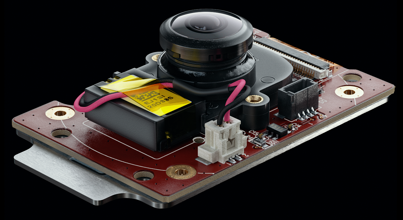
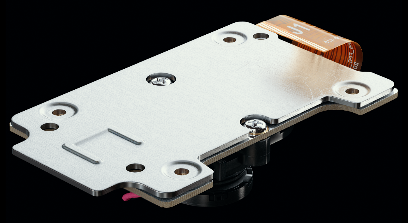
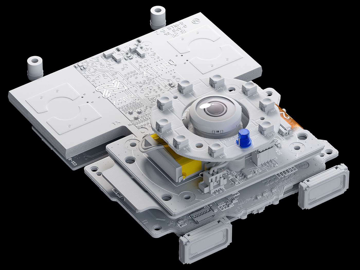
Camera Assembly test renders
Working on the layered masks for the Memory Controller PCB
Memory controller PCB test renders
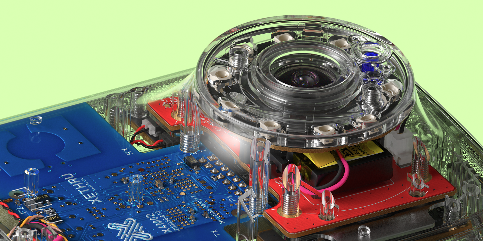
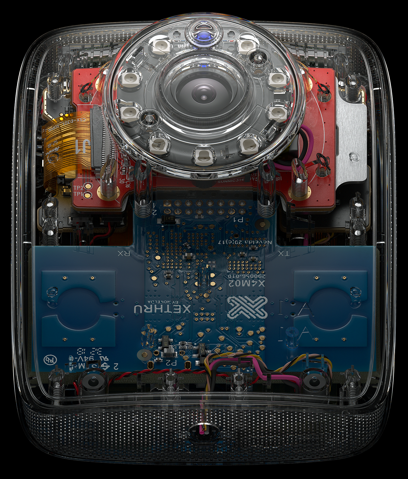
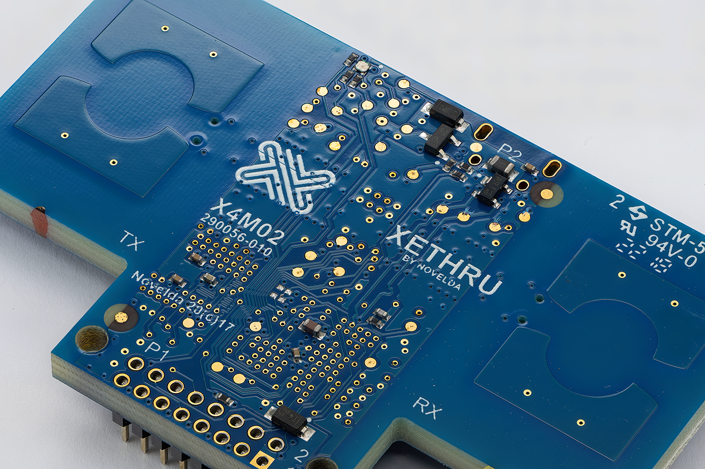
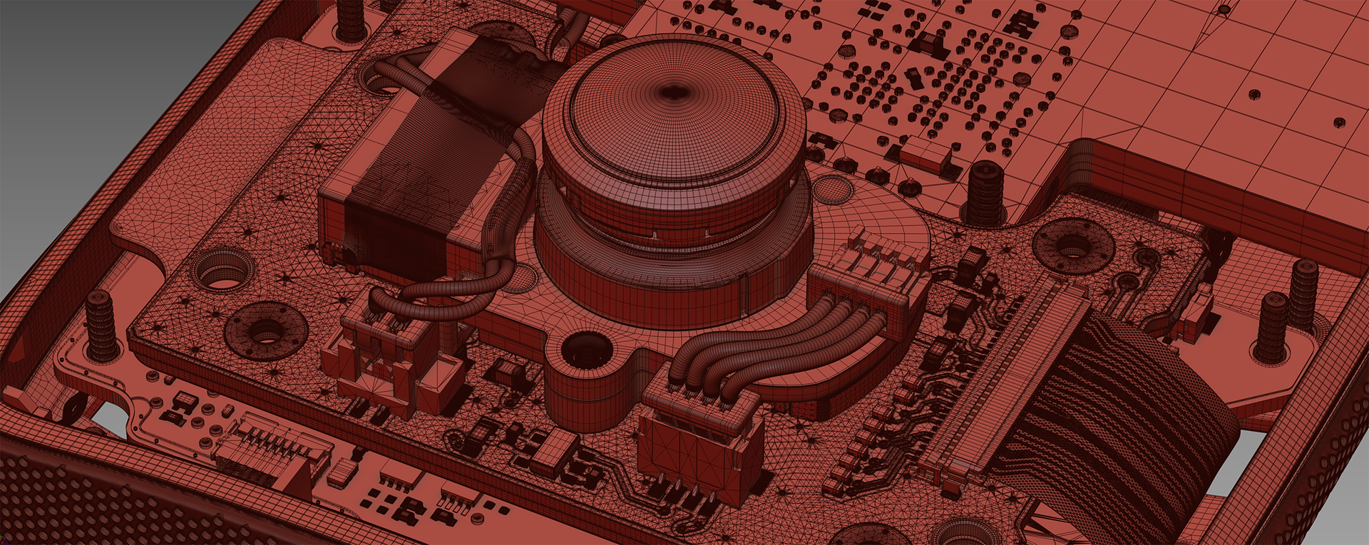
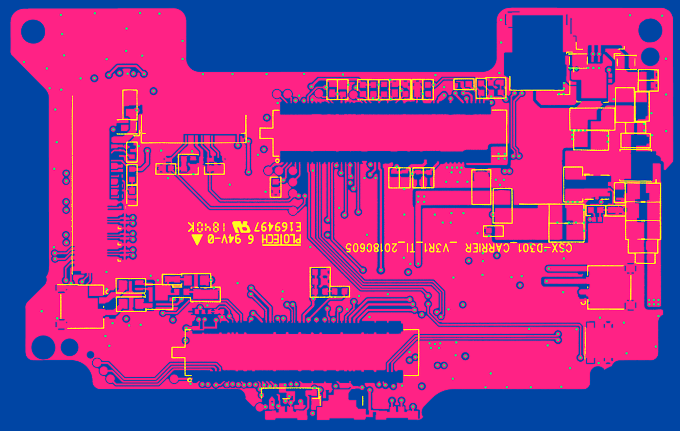
However, the most exciting part for me was working on the large blue PCB — the sensor controller “Radar Sensor SoC Board.”
It’s a double-sided, multilayer PCB assembly with numerous paths and an intricate, complex layout.
Because it’s relatively thick (4 mm) and the top varnish layer is semi-transparent, the board allows a lot of light to pass through, tinting it a deep blue.
Because it’s relatively thick (4 mm) and the top varnish layer is semi-transparent, the board allows a lot of light to pass through, tinting it a deep blue.
With so much light traveling through the fiberglass layers, you can even see additional layers of copper plates inside, casting subtle shadows within the material.

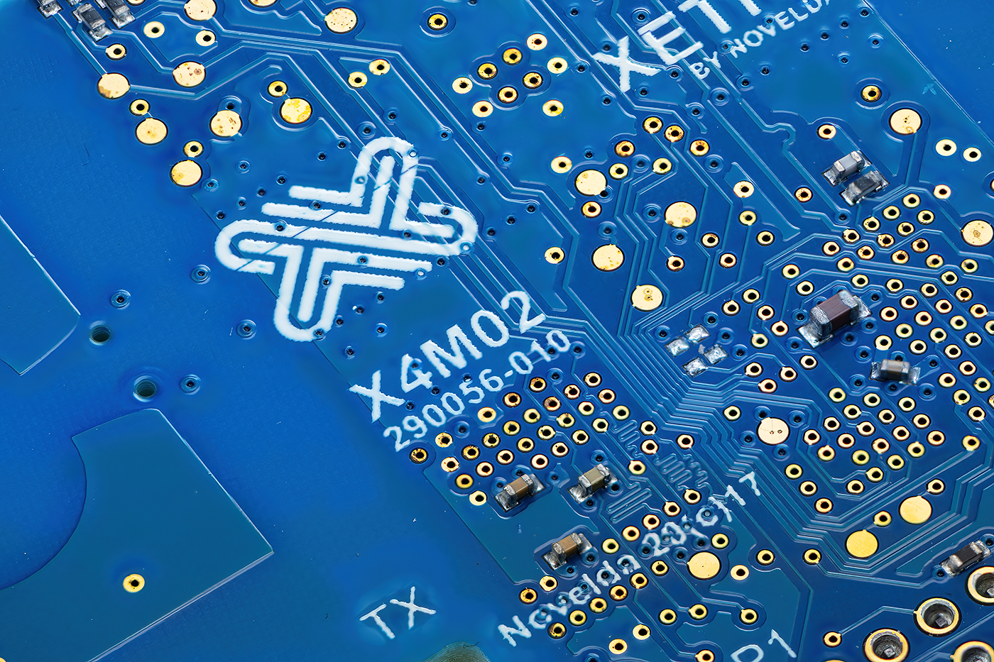
Radar Sensor SoC Board reference photo closeup
It was a real challenge that required an in-depth study in all aspects. In addition, the top layer of the coating was so thick that it created the effect of "glazing" the paths on the board's surface.
From the beginning, it became clear that it would be challenging and time-consuming to achieve such a look using real-geo modeling, which prompted me to choose a technique based on textures.
It was also not evident whether it would be possible to achieve this effect using procedural methods or I would have to use 3D sculpting methods to get the proper displacement height maps.
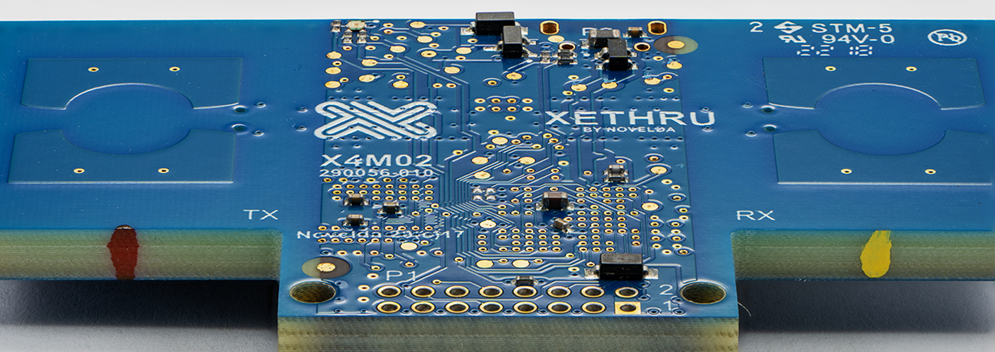
Radar Sensor SoC Board reference photo
Finally, I achieved a good result using a combination of the parallax bump method (a technique that allows you to achieve quality comparable to the micro-displacement at the normal-mapping speed) and multilayered bump texture generation using a mix map in FStorm render engine.
The final height map has seven layers mixed with masks with different amounts of blur. To increase the rendering speed, I used blurring of individual masks in Photoshop because procedural blur during the calculating before rendering takes a lot of time due to the high resolution of the textures.
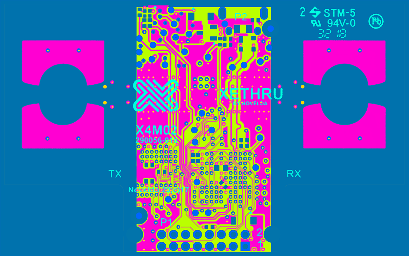
Working on the layered masks for the Radar Sensor SoC PCB
I also added some geometry layers inside the board to create a sense of internal shadow and uneven light penetration.
The golden contact plate geometry has a procedural blend with the PCB surface, enhancing the glazing effect.
The golden contact plate geometry has a procedural blend with the PCB surface, enhancing the glazing effect.
I deliberately avoided adding any imperfections such as dust, dirt, wear marks, or grease marks.
Radar Sensor SoC Board rendering WIP

Shading network for the Radar Sensor SoC Board
Working on the PCB assembly.
Render and final postwork
Using real-time GPU rendering allowed me to keep post-processing work to a minimum. Mainly I worked with contrast.
To be able to adjust individual elements, I used RGB masks, some of which themselves look like art objects.
Each frame was rendered at 4k wide resolution on a 2x RTX 3090ti PC. The average render time for a frame was 15 - 35 minutes. In some cases, such as rendering with a transparent case body, the time increased up to 1 hour per frame.
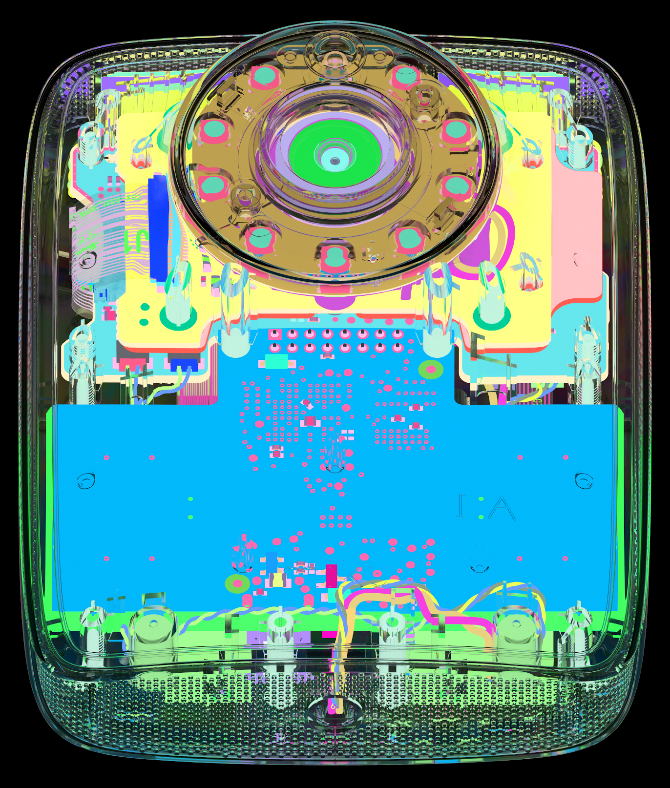
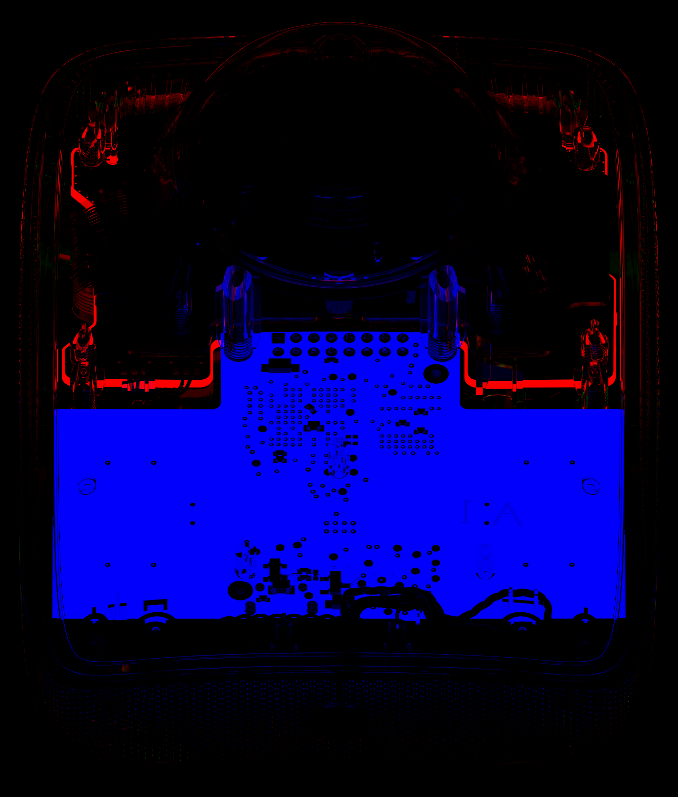
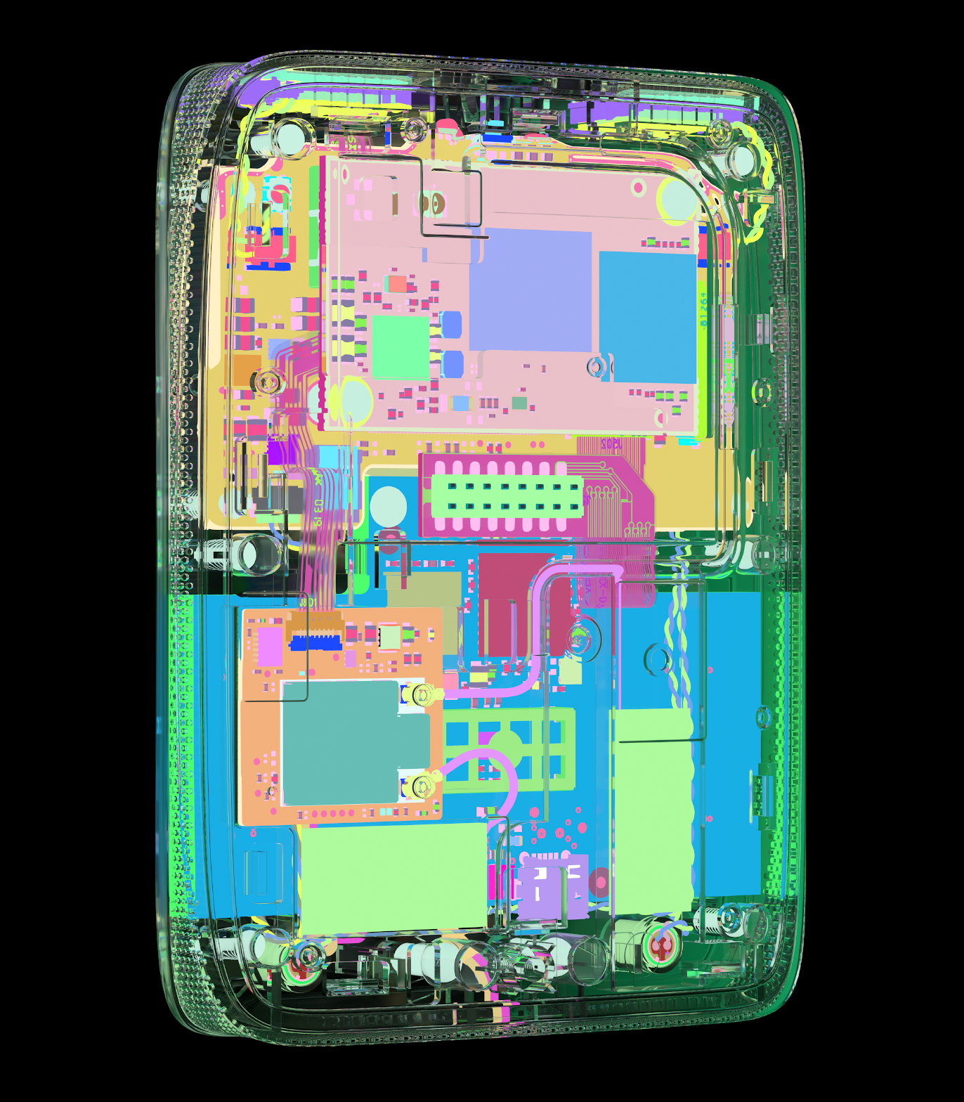
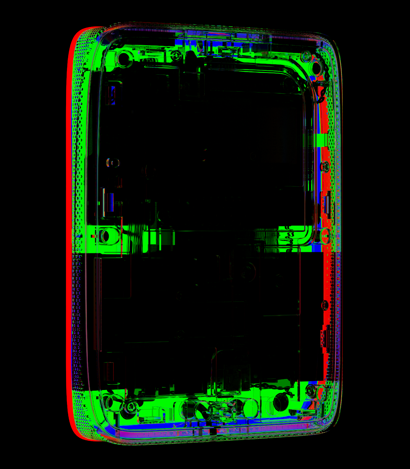
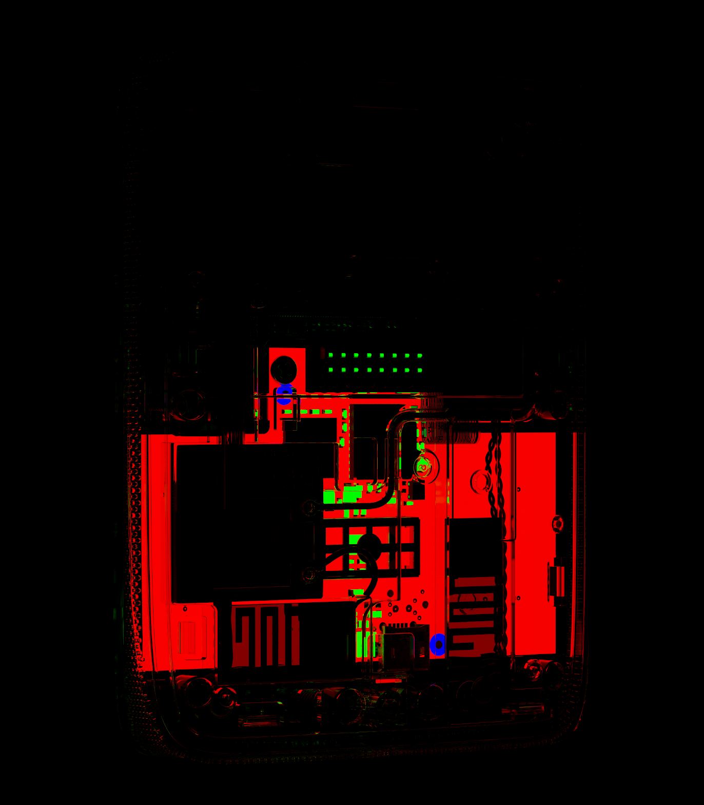
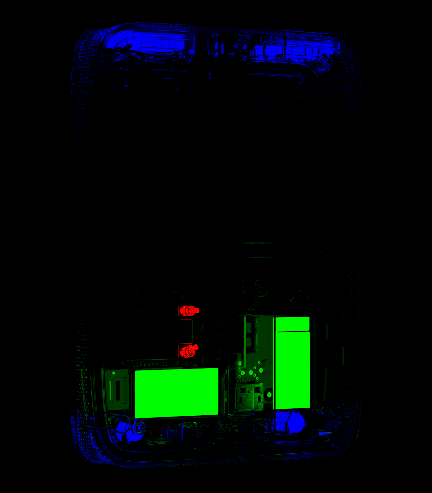
Object ID render Pass for the transparent case shots.
Thank You